soundaatma,
thanks for your kind words.")
In general tweeters with 4" faceplates or with (big) ferrite magnets won't work properly as bipoles.
Rudolf
thanks for your kind words.
I didn't look into bipoles because I want narrow dispersion, not a wider one.Did you also experiment with the two tweeters wired in phase thus making a bipole tweeter.
A 1" dome dipole would better a 1" bipole above 3 kHz. That is with a 3x3 cm "baffle" between the back-to-back tweeters. Don't try a much wider baffle (6x6 cm for instance) because that would ruin the radiation homogenity of the bipole.Compared to dipole phasing, believe a bipolar phasing would have the benefit of :
1)no dipole cancellation and hence lower cutoff
Near omnipolar radiation only as long as the baffle is small enough. With a 6x6 cm baffle (which equals a 3 cm distance between front and rear dome) the directivity will fluctuate somewhat above 5 kHz.2)wider dispersion due to wrap around from the opposite tweeter, providing near omnipolar radiation before beaming starts.
In general tweeters with 4" faceplates or with (big) ferrite magnets won't work properly as bipoles.
Rudolf
No good idea at allI was actually planning a bipole using the Pluto driver Aurasound NSW2-326-8AT . Mounted back to back as close as possible, to be used from 500Hz and up, with bipole phasing to resemble an omnipole to the extent possible.
I simulated the situation with two Visaton BF45, which appear to have somewhat similar dimensions, in Boxsim:

I mounted both drivers at just 6 cm distance, which wouldn't even let room for the rear exits of the Auras to breath. You can see how the on-axis response almost immediately becomes a mess. The off-axis response isn't any better:

The directivity index finally proves that this configuration isn't worth any further thought
: 
Thanks for the sims on Boxsim Rudolf.
The bipole dip is clearly evident in the sims. However for a 6cm distance between the drivers I was expecting the half wavelength bipole dip when the 2 waves meet out of phase at about 2800Hz. Anyway the polar response disarray is nasty. Was not expecting this for a bipole. Guess I have to follow the advice of making the cabinet wider than deeper, to allow the baffle step fill in the bipole dip
The bipole dip is clearly evident in the sims. However for a 6cm distance between the drivers I was expecting the half wavelength bipole dip when the 2 waves meet out of phase at about 2800Hz. Anyway the polar response disarray is nasty. Was not expecting this for a bipole. Guess I have to follow the advice of making the cabinet wider than deeper, to allow the baffle step fill in the bipole dip
The distance between the drivers has to be calculated from the ears (where it counts).To the nominal 6 cm distance between the drivers you have to add the distance from the rear driver rim to its center, which is another 2+ cm.However for a 6cm distance between the drivers I was expecting the half wavelength bipole dip when the 2 waves meet out of phase at about 2800Hz.
If interested, you might try to mount the drivers one below the other. This could reduce the effective driver distance, but would certainly lead to other problems.
No good idea at all
I simulated the situation with two Visaton BF45, which appear to have somewhat similar dimensions, in Boxsim:
Hi Rudolf,
could you sim two slim tweeters (like scan-speak 710003 with the 6 magnets) in a round baffle about 20cm diameter and 10cm thick (to enclose the motors and some stuffing)? ah, connected in series.
I'm not sure if this worth my time, but since you are curiousHi Rudolf,
could you sim two slim tweeters (like scan-speak 710003 with the 6 magnets) in a round baffle about 20cm diameter and 10cm thick (to enclose the motors and some stuffing)? ah, connected in series.
:
I simulated the Visaton SC10 which should be equal enough in its geometry. Boxsim doesn't do circular baffles, so I made it 18x18 cm square. Depth is 10 cm, drivers in series.
I add the boxsim file for this simulation as .zip. Note that it is not zipped. Just download it and change ".zip" to ".bpj" and you can open it in boxsim.
View attachment Bipole SC10.zip
Yes, you can point any driver to any of the speaker geometry axis - x,y,z.Rudolf- a slightly off topic question, but im interested in simming 2 tweeters in side panels. Im quite competant using Boxsim, but im unsure if it is possible to simulate this.
Select driver x from the "Drivers & Enclosures" menue (where you select/change drivers).
At the top of the "Edit driver" window select the tab "Baffle and position".
The lower third of the window starts with the selection "Direction of beam". Select as you wish.
The position of the driver in space has to be given in xyz coordinates below. You can't do that in the "Common outer housing" window. Working with those xyz coordinates can be tricky. You could tell me, where you want your drivers on the side panels and I could position them in a "test" .bpj-file. Or you could start by yourself and let me look into it afterwards (if you feel so).
Rudolf
I have very little math skill or measurement tools , but I have gotten very good results from the Neo3 in isobaric use where the distance between the membranes are @ equal to the cross over frequency. Paired with a Neo 10 in a helmholtz resonant tuned to 200hz enclosure with a 19 mm long port , @ 10cm wide, this fills in most of that drivers response to midbass while pretty much being a dipole to match the tweeters' dispersion. Has anyone noticed how good the nos military pio and polystyrene caps are these days?That's exactly what I believe too.
Agreed again. And I don't see a practical way to 'tune' them to even better performance with diy means.
But there are two caveats:
1. Different manners to produce directivity lead to different expansions of the directivity function WRT angle. Would dipole directivity merge seamlessly with WG directivity?
2. If you want a WG to stretch 3 octaves, it needs to be rather deep. Put two of them back to back to get some sort of figure 8 pattern - and they will get de-correlated quite easily.
I worked my way through the entire thread today, skipping some parts. The measurements on back-to-back domes shown in the first few pages look quite good, yet the overall opinion seems to still be that a true dipole tweeter is better. Rudolf, why is that? Do you still use back-to-back domes?
Last edited:
My educated guess is that simply because the difference in spatial location of radiating membrane of back-to-back tweeters. Dipole cancellation at high frequencies comes very sensitive to that (short wavelength). Even with a nude planar Neo3PDR dipole null comes at around 6kHz. Delaying doesn't change pysical time alignment of BB, it just shifts the comfort zone!
Rudolf, please give a more articulated and scientific answer!
Rudolf, please give a more articulated and scientific answer!
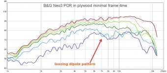
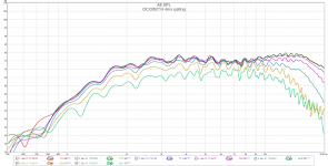
OllBoll, looks like you have quite long IR gating and too many reflections. What was distance? We should be able to see more spl change there and lower spl at 60-90deg.
4ms gating no smoothing should be fine, but first check the impulse response to see first reflection.
But anyway, it seems to work well! how about 90-180 deg?
4ms gating no smoothing should be fine, but first check the impulse response to see first reflection.
But anyway, it seems to work well! how about 90-180 deg?
Last edited:
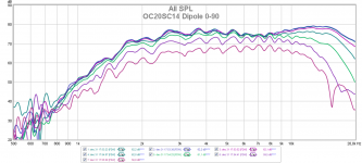
Oh yes and was there any xo or eq applied, to make on-axis response smooth?
Sweep start frequency can be around 1kHz to prevent damage, eg. . This little baby's resonance it t 1,6kHz, so be careful!
OC20SC14-04 – Tymphany
SC02 has lower Fs 1,1kHz Peerless OX20SC02-04 20mm Fabric Dome OX Tweeter 4 Ohm
Sweep start frequency can be around 1kHz to prevent damage, eg. . This little baby's resonance it t 1,6kHz, so be careful!
OC20SC14-04 – Tymphany
SC02 has lower Fs 1,1kHz Peerless OX20SC02-04 20mm Fabric Dome OX Tweeter 4 Ohm
Last edited:
OllBoll, looks like you have quite long IR gating and too many reflections. What was distance? We should be able to see more spl change there and lower spl at 60-90deg.
4ms gating no smoothing should be fine, but first check the impulse response to see first reflection.
But anyway, it seems to work well! how about 90-180 deg?
You are right that I probably had a bit too long gating so here is the same measurements with some shorter gatings:
But yeah you are right that the 60-90 should probably be lower, I might not have had the angles perfectly and with the mic distance of ~ 50 cm and measuring in a room that will probably also hide some of the null.
And on 90-180. This is two of the tweeters glued back to back so 90-180 is same as 0-90.
Attachments
- Home
- Loudspeakers
- Multi-Way
- On the directivity of dipole tweeters