There have been some attempts lately to make dipole tweeters work up to high frequencies with constant directivity. How high can we go, if the tweeter housing is already almost as small as its radiating area?
I would like to demonstrate the issues involved with an idealized 1 inch circular tweeter. I am using some Boxsim simulations to show things detached from specific driver peculiarities like FR and dome breakup modes.
Let’s start with the mathematical dipole model – first for a dipole distance of 2,5 cm to keep things within 20 kHz:
This is equivalent to this Linkwitz figure.
A 1’’ tweeter would have a physical diameter of at least 2,5 cm. This would lead to a dipole distance of 1,25 cm. As a 2-point source this would sim like this:
Of course a tweeter is no 2-point source. Let’s first move to a dipole point source on a 25x25 mm square baffle (Boxsim can’t do circular baffles).
We can see that the dipole peaks are slightly lower in frequency because a 25x25 mm baffle is more like a 28 mm disc than 25 mm. More important by far is the change in directivity that is introduced by the baffle. The dipole 8 gets sort of slimmer.
Since a real tweeter is not a point source on a baffle, we make the cone/dome/foil as wide as the baffle. Note that our model is working as a dipole membrane in a housing with no depth now. Any real world tweeter would have to be larger:
Note how the dipole 8 gets even slimmer than before and how the dipole peaks move to even lower frequencies. Strangely the 60 deg peak is at a lower frequency than the on-axis peak. Same for 30 deg. How come? The next diagram shows why by overlaying the last two diagrams:
The wider source starts to beam – lower in frequency at wider angles. From a certain frequency up the directivity of the tweeter is no longer controlled by the dipole function but by the tweeter diameter. The next diagram shows this relationship at the first dipole peak:
A monopole tweeter would have a main beam to the front of almost the same contour as the figure 8 of the dipole. This would be true for any driver whose radiating area is as large as its baffle – regardless of size. Any attempt to manipulate the radiation at the sides of the baffle is quite fruitless for frequencies above the first dipole peak – they don’t show up any longer at the sides.
The only cure is to move the first dipole peak up by making the tweeter smaller. Above the first dipole peak all compact drivers will move from the (constant) directivity of the dipole 8 to the frequency dependent directivity of a beaming driver.
That’s how I see it.
Attachments
I've been doing similar simulations with Tolvan Edge. A point source on a 2 mm wide circular baffle looks nice. It would need a couple of centimeters excursion though. Perfect dipole treble seems impossible in the real world. Drivers such as the Mundorf and the Neo3W seem good practical dipole tweeters.
I think the only way to extend constant directivity without these issues would have to be waveguided tweeters.
I think the only way to extend constant directivity without these issues would have to be waveguided tweeters.
That's exactly what I believe too.Perfect dipole treble seems impossible in the real world.
Agreed again. And I don't see a practical way to 'tune' them to even better performance with diy means.Drivers such as the Mundorf and the Neo3W seem good practical dipole tweeters.
But there are two caveats:I think the only way to extend constant directivity without these issues would have to be waveguided tweeters.
1. Different manners to produce directivity lead to different expansions of the directivity function WRT angle. Would dipole directivity merge seamlessly with WG directivity?
2. If you want a WG to stretch 3 octaves, it needs to be rather deep. Put two of them back to back to get some sort of figure 8 pattern - and they will get de-correlated quite easily.
That's exactly what I believe too.
Agreed again. And I don't see a practical way to 'tune' them to even better performance with diy means.
But there are two caveats:
1. Different manners to produce directivity lead to different expansions of the directivity function WRT angle. Would dipole directivity merge seamlessly with WG directivity?
2. If you want a WG to stretch 3 octaves, it needs to be rather deep. Put two of them back to back to get some sort of figure 8 pattern - and they will get de-correlated quite easily.
I've only been contemplating the idea of using WG's to extend controlled directivity to higher frequencies only recently. There are indeed practical problems, of which I am not sure they can be overcome. I've never worked with waveguides, but I think there are possibilities. I might try it for a next project. However, the Neo3W in an unbaffled configuration doesn't leave me wanting. I've rarely heard the highs this detailed - yet clean, without harshness.
Dipole tweeters in the real world
In post #1 I talked about a 1 inch dipole tweeter on a 1 inch circular baffle and with no depth. This is certainly a theoretical concept only. How near to that can we get with real world tweeters? Before we start I would like to refresh your knowledge of ‘dipole distance’. This is the distance from the middle of the rear dipole source to the plane of the front dipole source:
The dipole distance (red line) is shown for two dome tweeters back-to back in a tube (left), for a planar tweeter like the B&G Neo 3 (middle) and a small baffle with two vertically offset tweeters (right – more about that later). Note that the dipole distance will not vary around the perimeter for the tube, but it will vary for the rectangular constructions.
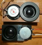
I have built two dome tweeter dipoles in the back-to-back fashion:
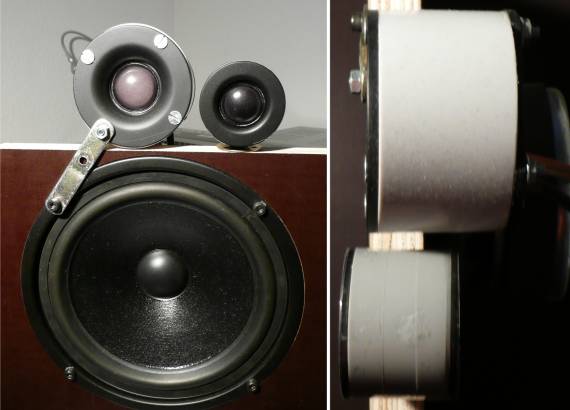
The bigger one is two Monacor DT-25N back to back in a tube of 3.3 cm radius and 4.4 cm depth (including the front plates of the tweeters). This adds up to a dipole distance of 7.7 cm, which would correspond as wavelength to a frequency of 4450 Hz. Let’s look at some measurements from 0 deg to 90 deg horizontal with a high pass filter at 2.5 kHz to protect the drivers. Shown are 0, 15, 30, 45, 60, 75 and 90 deg:
We see nice constant directivity from 1 kHz to almost 4 kHz. At 4.5 kHz - the wavelength of the dipole distance - the wave from the rear tweeter will need just a wavelength to reach around to the front - so no phase difference (or 360 deg) on axis to the wave from the front tweeter. Since both waves are 180 deg out of phase at the source, they will reduce each other. Hence we see a dip in the on axis frequency response. Above that dip the dipole CD gets lost and beaming takes over. You see that in the spreading of the off-axis-SPLs with rising frequency above 4.5 kHz.
You may have noticed that those DT-25N are really small tweeters. Two Seas Millenium tweeters mounted back to back (as used in Linkwitz’ Orion) would have a dipole distance of 13.7 cm. This corresponds to 2500 Hz. You simply can’t have dipole CD with them anywhere within their recommend frequency range.
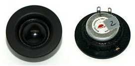
The smallest tweeters I could find where the Dayton ND20FA. You see a back-to-back dipole with them beside the Monacors in the picture. The dipole distance of the Dayton tweeter dipole is 5.6 cm ( 6125 Hz). I have measured their horizontal response too:

You see how the on-axis-dip has moved up to near 6 kHz. Below nice CD down from 4.5 kHz, above 6.5 kHz beaming (which does not show very well because some low pass got in the way above 10 kHz). This is as good as it gets with back-to-back tweeters.
I have borrowed a diagram from cuibono for the BG Neo3PDR planar tweeter:
Its dipole length of 4.1 cm (8575Hz) and some makes it probably the best CD dipole tweeter available today. As shown, the frequency range is in conjunction with a TB W4-1320sj, fully EQ'd and crossed at 1.7 kHz. The lines represent 0, 30, 45 and 60deg off axis. Of course you can see the CD area and the beaming area very well.
I have asked myself if it would be possible to undercut the dipole length of 4.1 cm. Voila:
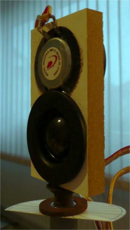
I placed two Dayton ND20FA-6 back to back, but vertically offset, on a small baffle (8 x 4.4 x 1.4 cm). This results in a dipole distance of 3.6 cm at minimum (9527 Hz). See the horizontal response (0, 15, 30, 45, 60, 75, 90 deg), measured at 45 cm distance:
Not too shabby, either, with that dip at 8 kHz.
You may think that the vertical response will be very bad, concerning the vertical offset of 3.4 cm between the driver centers. That’s what I did too. But measurements along the vertical axis show a benign response. Green line is the power response:

Time to do some decent bafflets for those ND 20FA. Here in Germany four of them cost as much as one Neo3.
In post #1 I talked about a 1 inch dipole tweeter on a 1 inch circular baffle and with no depth. This is certainly a theoretical concept only. How near to that can we get with real world tweeters? Before we start I would like to refresh your knowledge of ‘dipole distance’. This is the distance from the middle of the rear dipole source to the plane of the front dipole source:
The dipole distance (red line) is shown for two dome tweeters back-to back in a tube (left), for a planar tweeter like the B&G Neo 3 (middle) and a small baffle with two vertically offset tweeters (right – more about that later). Note that the dipole distance will not vary around the perimeter for the tube, but it will vary for the rectangular constructions.
I have built two dome tweeter dipoles in the back-to-back fashion:
The bigger one is two Monacor DT-25N back to back in a tube of 3.3 cm radius and 4.4 cm depth (including the front plates of the tweeters). This adds up to a dipole distance of 7.7 cm, which would correspond as wavelength to a frequency of 4450 Hz. Let’s look at some measurements from 0 deg to 90 deg horizontal with a high pass filter at 2.5 kHz to protect the drivers. Shown are 0, 15, 30, 45, 60, 75 and 90 deg:
We see nice constant directivity from 1 kHz to almost 4 kHz. At 4.5 kHz - the wavelength of the dipole distance - the wave from the rear tweeter will need just a wavelength to reach around to the front - so no phase difference (or 360 deg) on axis to the wave from the front tweeter. Since both waves are 180 deg out of phase at the source, they will reduce each other. Hence we see a dip in the on axis frequency response. Above that dip the dipole CD gets lost and beaming takes over. You see that in the spreading of the off-axis-SPLs with rising frequency above 4.5 kHz.
You may have noticed that those DT-25N are really small tweeters. Two Seas Millenium tweeters mounted back to back (as used in Linkwitz’ Orion) would have a dipole distance of 13.7 cm. This corresponds to 2500 Hz. You simply can’t have dipole CD with them anywhere within their recommend frequency range.
The smallest tweeters I could find where the Dayton ND20FA. You see a back-to-back dipole with them beside the Monacors in the picture. The dipole distance of the Dayton tweeter dipole is 5.6 cm ( 6125 Hz). I have measured their horizontal response too:
You see how the on-axis-dip has moved up to near 6 kHz. Below nice CD down from 4.5 kHz, above 6.5 kHz beaming (which does not show very well because some low pass got in the way above 10 kHz). This is as good as it gets with back-to-back tweeters.
I have borrowed a diagram from cuibono for the BG Neo3PDR planar tweeter:
An externally hosted image should be here but it was not working when we last tested it.
Its dipole length of 4.1 cm (8575Hz) and some makes it probably the best CD dipole tweeter available today. As shown, the frequency range is in conjunction with a TB W4-1320sj, fully EQ'd and crossed at 1.7 kHz. The lines represent 0, 30, 45 and 60deg off axis. Of course you can see the CD area and the beaming area very well.
I have asked myself if it would be possible to undercut the dipole length of 4.1 cm. Voila:
I placed two Dayton ND20FA-6 back to back, but vertically offset, on a small baffle (8 x 4.4 x 1.4 cm). This results in a dipole distance of 3.6 cm at minimum (9527 Hz). See the horizontal response (0, 15, 30, 45, 60, 75, 90 deg), measured at 45 cm distance:
Not too shabby, either, with that dip at 8 kHz.
You may think that the vertical response will be very bad, concerning the vertical offset of 3.4 cm between the driver centers. That’s what I did too. But measurements along the vertical axis show a benign response. Green line is the power response:
Time to do some decent bafflets for those ND 20FA. Here in Germany four of them cost as much as one Neo3
.Attachments

Last edited:
Member
Joined 2003
Vifa OX20SC00-04 might also be interesting to try.
Wow! That Vifa is really small - but sadly seems to be unobtainium here around
Next candidate for a step up in quality for me would be the Monacor DT-25TI with the face plate cut off.
An externally hosted image should be here but it was not working when we last tested it.
I'm taking my hat off to any foreigner who is trying to understand Boxsim in German!mow i need to learn more German so i can try an do some interesting sims too as i only use as much as i understand in german language

The text in Boxsim would be foreign language for most Germans too.
There has been some initiative to get an english version of Boxsim. Trouble is that the complete text is imbedded in the code - no separate language database. So UweG - the coder - shies away from excising all those textstrings.
...
Perfect dipole treble seems impossible in the real world
...
With distributed mode transducers one can get larger than wavelength
without beaming. Dipole radiation is a natural way to use a DML.
Kind regards
A man has to do what a man has to do ...
Am I completely nuts?

I cut the front plates of two Dayton ND20FA to the minimum and glued them roughly together without any baffle. You can compare the size to the previous baffle above. Dipole length now is 3.1 cm.
Then the same horizontal measurement procedure as before:
Since I could not believe what I saw, I did the same for the backside of the dipole tweeter and moved to the other 90deg side:
Green lines are for power response. Don't know why the 75deg response for the first diagram did not come up like that for the second series.
Tell me that this can't be true. Both drivers together are under 19 Euro. One BG Neo3 is 79 Euro in Germany.
Am I completely nuts?
I cut the front plates of two Dayton ND20FA to the minimum and glued them roughly together without any baffle. You can compare the size to the previous baffle above. Dipole length now is 3.1 cm.
Then the same horizontal measurement procedure as before:
Since I could not believe what I saw, I did the same for the backside of the dipole tweeter and moved to the other 90deg side:
Green lines are for power response. Don't know why the 75deg response for the first diagram did not come up like that for the second series.
Tell me that this can't be true. Both drivers together are under 19 Euro. One BG Neo3 is 79 Euro in Germany.
Attachments
Will this be a little more 'convenient':
Parts-Express.comayton ND16FA-6 5/8" Neodymium Dome Tweeter | tweeter nd16fa-6 soft dome tweeter dome tweeter neodynium dayton audio dayton loudspeaker dayton
or this:
Parts-Express.comayton ND20FB-4 Rear-Mount 3/4" Neodymium Dome Tweeter | tweeter nd20fb-4 soft dome tweeter dome tweeter neodynium dayton audio dayton loudspeaker dayton zdt35-60608 POTT-080108 DayAudiTweetWoofMid050109
Parts-Express.com
ayton ND16FA-6 5/8" Neodymium Dome Tweeter | tweeter nd16fa-6 soft dome tweeter dome tweeter neodynium dayton audio dayton loudspeaker daytonor this:
Parts-Express.com
ayton ND20FB-4 Rear-Mount 3/4" Neodymium Dome Tweeter | tweeter nd20fb-4 soft dome tweeter dome tweeter neodynium dayton audio dayton loudspeaker dayton zdt35-60608 POTT-080108 DayAudiTweetWoofMid050109One BG Neo3 is 79 Euro in Germany.
You can get it for 49€ in France
It is rare that things are cheaper in France.
Yeah. When I started with cutting the drivers front plate, I expected to push that dipole irregularity 0.5 kHz up at the upmost. Really did not expect it to almost vanish. But obviously those last mm can make a vast difference.Wow, that's really impressive. And just when we'd all agreed that dipole up to 20kHz was impossible
Can you remove the front plate from the ND20 to cut it down or do you just mask off the dome and cut it?
No removable front plate. But you can easily saw or cut around the magnet housing from the backside. Quite soft plastic, no danger of anything chipping away. I did mask off the dome, yes.
Instead of simply glueing the drivers together - as I did - it could be a good idea to make a pair of mounting flanges like this:
Not really. The ND16FA is just a 16 mm instead of 20 mm dome in a housing of the same size. That is no deal IMHO.Will this be a little more 'convenient':
Dayton ND16FA-6 5/8" Neodymium Dome Tweeter
or ... Dayton ND20FB-4 Rear-Mount 3/4" Neodymium Dome Tweeter
The ND20FB-4 is larger in both directions. Both tweeters have more of a waveguide in front than the ND20FA. I fear that they might develop some sort of horn directivity before the dipole directivity disappears.
Thank you, nice to know. The German import only sells a special PDR-I version.You can get it for 49€ in France
It is rare that things are cheaper in France.
The vertical distance of the drivers is 2 mm less than in the previous version. So the vertical balance should be no worse than before. I will do new measurements some time this week.Hello Rudolf,
For vertical angles i would expect some more disturbances,
but when that configuration is mounted at the right height
that should be neglegible in practice.
Thanks to everybody for your appreciation of my work
Rudolf
Attachments
- Home
- Loudspeakers
- Multi-Way
- On the directivity of dipole tweeters