Hi guys,
been reading all this with great interest. I am using some AMT's I bought some time back for about 100€ each as dipole tweeters. They may not be the best available but I love the sound I get. I have never thought about their directivity as I seem to get good dispersion and AMT's, like ribbons are natural dipoles. Has anyone run any tests on the directivity of AMT's. For me they sound very fast and create good soundstage and can be crossed fairly low.
microx
You have to say which particular AMTs. If you are talking about the orriginal Heil large AMT, I'm guessing it is pretty good in the horizontal plane. It is quite close to the horizontal cross section of a 90 degree diffraction slot type horn, so it should have a 90 degree wide polar up to a fairly high frequency. It could be imporved at the low end with an end flare, much like the JBL CD horns have.
Vertically is a different story as the element is quite long and will be very beamy in the vertical plane.
Didn't Heyser or Keele measure the system in Audio magazine?
David S.
Edit: looking back in the thread I see its been done!
Last edited:
1) I'll try to do subjective test of changing polarity of rear HF drivers from direct to inverted;
2) to take directivity measurements by rotating the speaker and see what type of carrot/flare/whatever it gives for directivity (rear and front) and what kind of "eight" I'll have
We'll be back in a week or so.
Jānis,
that is terrific! I happen to have some of the W300 lying around here. Starting from their size the minimum "back-to-back package" size would be 16 cm diameter and ~16 cm depth. If your package stays within 20x20 cm, I would reckon a microfone distance of 60 cm (from the center of the package) to be sufficient to do qualitative measurements. Such measurements can be done in room without much hassle.
I found 0-90° in 10° intervals sufficient to get a good picture of what is happening. 5° only, if you see very rapid change between 10° FR. measurements.
If I am allowed to express wishes: I would like both dipole and bipole measurements of the HF unit, measured on driver height and with MF + LF units NOT in action.
Rudolf
Jānis,
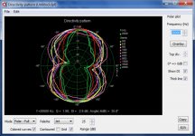
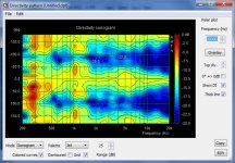
That room is really small, but the data are already meaningful IMHO. Was any gating applied? Probably things would become even more meaningfull when taken from half the distance.
Is the 15°(?) rotation of the polars intended? I would be very keen to play with your measurement data set myself. The sonogram for instance would show more detail above 2 kHz if you cut it off at 500 Hz.
What I already see is something looking like an axial response hole at 1 kHz (as theory predicts) and some blooming around 5 kHz. But by and large the polars look better than I expected.
You got a PM.
Rudolf
Rudolf,
No PMs so far
Being full-time help for my wife with two infants I roughly had three hours to build rotating panels with angle marks and make measurements. So I went for 15 degrees to at least get the rough picture.
Sine swept so no gating aplied.
Yes, the room is small but there are doorways on boths sides of mic that extends for 3m to other rooms, so it's somewhat okay.
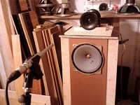
To add more matter for judgement I took a quick picture of the "lab"

I'm thinking about using naked Visaton FRS5X in vertical line array (somewhere between 25 and 36 of them). In your opinion, will they have enough output to be useable down to ~500Hz?
If you use 20 of them, Sd=13 cm² will add up to 260 cm². That's like a large 20 cm driver - with Xlin=0,6 mm. I wouldn't consider that "usable" at 500 Hz for the amount of money involved.
Starting at 1 kHz would be completely another world IMHO.
Jānis was so kind to send me his measurement data for the above waveguide dipole. He had measured 360° around the construction. For the following I took only two 90° segments to underpin some theory of mine. I don’t show polars, but the 15° stepped frequency response data:
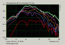
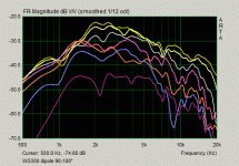
All data have been gated before the first reflections, corresponding to a 2 ms (60 cm) free zone. They are 1/12 oct smoothed. (The green line in the first diagram is the 1/3 oct smoothed response at 0°. That’s the reason why it says 1/3 oct above the picture)
We can easily see where the waveguide “shaping” sets in at 1.5-2 kHz. But in that “waveguide zone” above 2 kHz things look a bit messed up. Measurements with only one driver connected could show us, whether that waveguide is inferior or if something else has gone in the way. I believe the latter
I need to make a large detour to come to my point. Sorry for that.
This is a 3” driver in the center of a 22x22 cm square OB (upper part) and the same driver without any baffle in the lower part. There is a bit of driver EQ applied in the upper measurements:
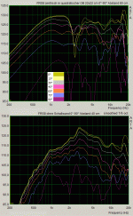
In the upper part we see a very prominent first dipole notch at 2.5 kHz and the dipole peak at 1-2 kHz. This is completely as would be expected. I would like to direct your attention to something else: Left from the notch all angle data are smoothly and parallel. Right from the notch things are quite disturbed. This disturbance is NOT due to the driver. It is a “function” of the large “dipole length” or dipole separation distance provoked by the OB.
When we leave off the baffle (lower part) the same driver behaves very well above the dipole peak – up to 10 kHz.
Now please look again at the first two diagrams in this post. Curious eyes will detect the dipole peak at ~ 800 Hz and the dipole notch at just above 1 kHz. They are not as developed as in the flat OB, because the sources are somewhat hidden inside the WG. What we see can be assigned to a large round baffle with ~25 cm radius, equivalent to dipole separation distance. 25 cm would add up from 8 cm waveguide radius plus 17 cm distance from the rear WG to the front WG.
For illustration I add both situations as EDGE sims:
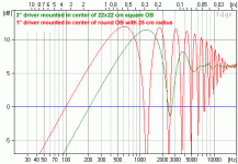
It is obvious that the WG part of the W300 dipole is completely operating in the “messy” region above the dipole notch.
Remember: Above is completely theorizing of mine.
It would need added bipole and monopole measurements to see if I am right or just fantazising. 0-90° measurements would be sufficient in all cases.
Rudolf


All data have been gated before the first reflections, corresponding to a 2 ms (60 cm) free zone. They are 1/12 oct smoothed. (The green line in the first diagram is the 1/3 oct smoothed response at 0°. That’s the reason why it says 1/3 oct above the picture)
We can easily see where the waveguide “shaping” sets in at 1.5-2 kHz. But in that “waveguide zone” above 2 kHz things look a bit messed up. Measurements with only one driver connected could show us, whether that waveguide is inferior or if something else has gone in the way. I believe the latter
I need to make a large detour to come to my point. Sorry for that.
This is a 3” driver in the center of a 22x22 cm square OB (upper part) and the same driver without any baffle in the lower part. There is a bit of driver EQ applied in the upper measurements:

In the upper part we see a very prominent first dipole notch at 2.5 kHz and the dipole peak at 1-2 kHz. This is completely as would be expected. I would like to direct your attention to something else: Left from the notch all angle data are smoothly and parallel. Right from the notch things are quite disturbed. This disturbance is NOT due to the driver. It is a “function” of the large “dipole length” or dipole separation distance provoked by the OB.
When we leave off the baffle (lower part) the same driver behaves very well above the dipole peak – up to 10 kHz.
Now please look again at the first two diagrams in this post. Curious eyes will detect the dipole peak at ~ 800 Hz and the dipole notch at just above 1 kHz. They are not as developed as in the flat OB, because the sources are somewhat hidden inside the WG. What we see can be assigned to a large round baffle with ~25 cm radius, equivalent to dipole separation distance. 25 cm would add up from 8 cm waveguide radius plus 17 cm distance from the rear WG to the front WG.
For illustration I add both situations as EDGE sims:

It is obvious that the WG part of the W300 dipole is completely operating in the “messy” region above the dipole notch.
Remember: Above is completely theorizing of mine.

It would need added bipole and monopole measurements to see if I am right or just fantazising. 0-90° measurements would be sufficient in all cases.
Rudolf
It would need added bipole and monopole measurements to see if I am right or just fantazising. 0-90° measurements would be sufficient in all cases.
Rudolf
Exactly what I was going to do next. Thanks for additional research, it's nice to see some teamwork starting to take place here!
Thanks for sending me those .pir files.Exactly what I was going to do next.
Every single 90° quarter looks consistent. Yet I don't know, why they measure different. Shouldn't this dipole WG be highly symmetric? By which means do you rotate the thing?
When doing the first measurement set - did you measure in one turn, going from 0° to 90, 180 and 270° and ending at 0°? Or did you go from 0 to 180° and then starting again at 0°, turning it the other way around to 180°? I suppose it was the second way.
How far is the distance from the front WG plate to the rear one actually? I am just curious.
Cheers
Rudolf
Sure. Fun is why we all are here, right? Hard work starts when we start make something bigger out of the fun zone.
Right, due some hassle with the cable measurement was done "second way". Also, I had to duplicate +180° result also as -180° and leaving also +0° present. Otherwise I had strange gap in ARTAs directivity polar pattern between -15° and 0°. So this added -180 somehow sorted it out. Haven't got the time to figure out what is the right way to do it. Perhaps this "extra" made things "shift" a bit. ARTA authors could implement validation for such data or to point out in help file how to prepare full circle measurement data. Oh, right, I understand now. I have to had to duplicate +0 as -0 instead. So just delete -180 and make "negative copy" of +0 and see if that helps.
Speakers are duct taped with rear chambers close together, distance between fronts .
So now I'm going to:
a) re-run the test of 90° only with speakers inverted;
b) same but non-inverted;
c) same with rear speaker replaced with close RL equivalent.
In terms of measurement correctness my current setup will be knowingly "wrong" for c) as acoustic center for one speaker will be behind the speaker comparing to a) and b) "combo". For comparison (and convenience) sake I'll leave front speaker where it is also in c). We must take into account that in all three measurements on angled positions speakers will gradually move away from mic for several centimeters and angles will became little wider. That's one of reasons in favor measuring from 1m distance rather than 60cm as it reduces this error.
Any more suggestions so far?
I've found that a lot of off-axis messiness in waveguides improves with better termination. The back-to-backs are completely unterminated, and as such it's not surprising that they're very peaky. I have not seen such peaking, off-axis, in properly terminated horns. One easy solution (making a torus isn't easy!) is to use acoustic foam around the periphery of the device to soften the transition over the lip.
Oh, right, I understand now. I have to had to duplicate +0 as -0 instead. So just delete -180 and make "negative copy" of +0 and see if that helps.
Wrong guess, forget it
One easy solution (making a torus isn't easy!) is to use acoustic foam around the periphery of the device to soften the transition over the lip.
That's right, thanks for a hint. I believe the harder the enclosure the better, as less signal is lost as heat. Felt usage around edges was popular in old-timer studio monitors with hard edges. I got decent improvement of HF in my car by placing it properly. But that's completely different topic.
Regarding dual WG I have thought about half-circle "rainbow" shaped fat tube (D >30cm) that could extend waveguide outer edges so that transition back to back upwards and to the sides is smooth. For this I've made prototype out of bendable aluminium smoke tube and filled it with construction foam. After mild heating of tube with construction dryer the foam expanded quite nicely and fixed soft tube walls from inside. It's still far less stiff as wood but should be enough to measure the difference it makes (if any). We'll come to that later
Regarding dual WG I have thought about half-circle "rainbow" shaped fat tube (D >30cm) that could extend waveguide outer edges so that transition back to back upwards and to the sides is smooth. For this I've made prototype out of bendable aluminium smoke tube and filled it with construction foam. After mild heating of tube with construction dryer the foam expanded quite nicely and fixed soft tube walls from inside. It's still far less stiff as wood but should be enough to measure the difference it makes (if any). We'll come to that later
I'll be interested to see your construction, if it works well, could be quite the boon for other builders.
Good to know. Hopefully PRTG finds an effective way to "round off" the construction. Is there any hope that we can have the waveguides a bit more in free air too? As is, they are sitting on the floor - somehow.The back-to-backs are completely unterminated, and as such it's not surprising that they're very peaky. I have not seen such peaking, off-axis, in properly terminated horns.
Rudolf
- Home
- Loudspeakers
- Multi-Way
- On the directivity of dipole tweeters
