I posted some thoughts on reducing waveguide size on the "Geddes on Waveguides" thread. In particular, I am curious about the use of domes. While some have used domes in the past to reduce the cost of a waveguide, I am only interested in reducing the size of the waveguide.
So cost will not be a consideration for this project.
Anyways, if you're curious about waveguides, but are daunted by the sheer size of the devices, read on...
I personally own Gedlee Summas, and enjoy the performance of them, and heartily recommend them. At the same time, in the spirit of DIY, I'm curious to see how I can reduce the size of a waveguide.
Here is my original post from the other thread.
I gave up on using domes in waveguides a few years ago, but I think I'm ready to take another crack at it. I personally believe that a compression driver is a better solution, but I have a unique problem, and I can't find a way to solve it that doesn't involve a dome tweeter. Here's the situation:
I've built a ton of horns and waveguides, primarily for automotive use. When I first started, I built them full size. We're talking huuuge ol' horns that make the car basically undrivable. This is back in the 90s. As I began building waveguides, I found that you could use boundaries to extend the waveguide. And I don't mean an inch or two. I'm talking about removing over 75% of the waveguide.
Here's the problem I'm running in to: The size of the compression driver itself is really becoming an issue. I can't find compression drivers small enough to fit into corners. The best solution that I've found so far is to bend the throat of the waveguide, so that the compression driver enters at a 45 degree angle. But it's tricky, because the bend creates a dip in the frequency response, and the dip gets deeper as the bend gets bigger. (IE, if the compression driver enters the waveguide at a ninety degree angle you get a big fat dip due to a reflection off the wall of the waveguide.)
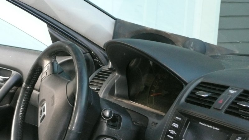
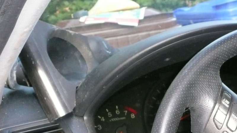 Here's the best waveguide I've built. It's an elliptical oblate spheroidal loaded by a BMS 4540ND. It has a horizontal coverage of 108 degrees, vertical of 72, and an average of 90. You can see that the compression driver enters at an angle. This allows me to push it as far back as possible on the dash of my car, which better mates with the angle of the dash and the windshield.
So here's what I'm thinking. If you a neodymium tweeter at the apex of a waveguide instead of a compression driver, you can push that waveguide almost all the way back. By pushing it back further, you can reduce the mouth of the waveguide even further. Basically, you let the windshield and the dash do more of the work.
Again, not saying that this is a good solution for the home, where depth isn't a problem. But my application is rather unique, and I simply can't think of another way to solve this.
By using a dome tweeter I will lose a great deal of efficiency, reduce power handling, and increase distortion. On the upside, it's smaller, looks better, and costs less. I have a hunch that a phase plug could be built to improve the high frequency polar response. Basically get the dome to behave more like a compression driver, and less like a dome.
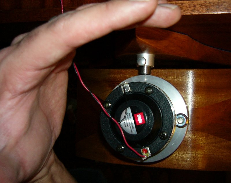
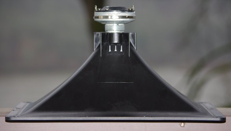
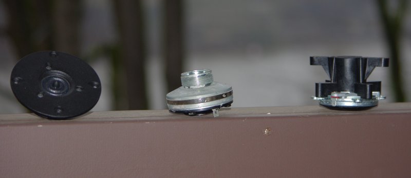
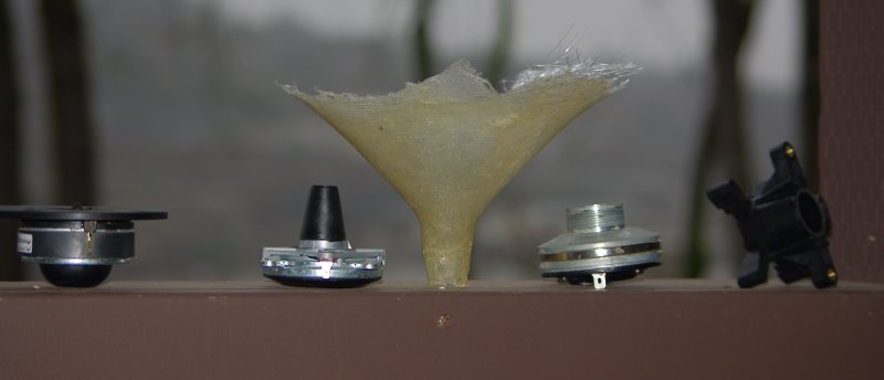
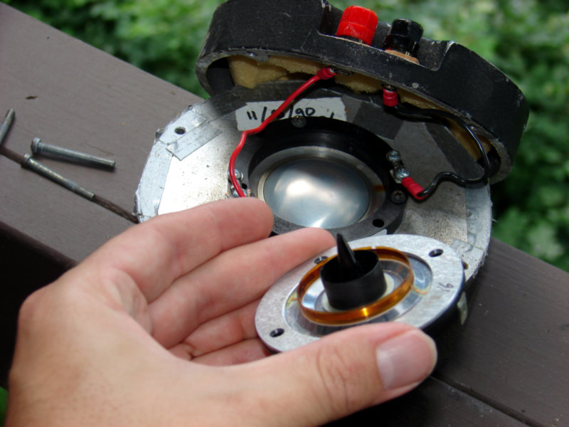 As I see it, a compression driver is a big dome tweeter with an extraordinarily powerful motor, and a carefully designed phase plug. Here are two compression drivers that I've used. JBL 2470 on the left, back when I was into huge horns in the car. BMS 4540ND in my hand, once I switched to Unity horns.
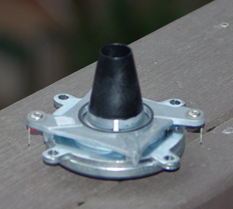
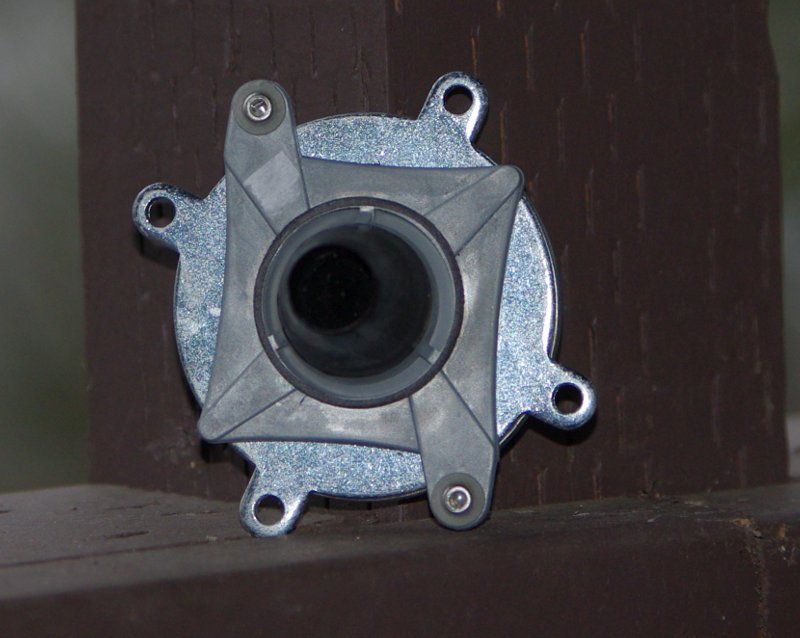
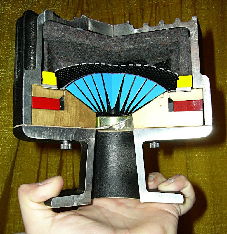 Here's a TAD compression driver cut in half. They had this laying around their demo room when I was there, a rather amazing paperweight if you ask me. In the cross section you can see that this isn't much different than a dome tweeter, except they've added a very carefully designed phase plug in front of the diaphragm, and the dome is inverted.
 To give you a sense of scale, here's the compression driver that I'm using in my car, mounted on a conventional horn. (woodhorn.com btw.) You can see that the TAD absolutely dwarfs it.
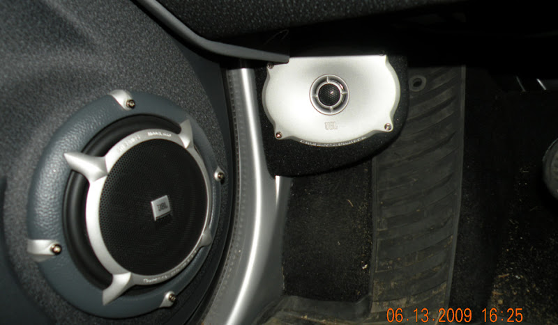
Here's a pic of JBL's top of the line components, which use a waveguide that looks suspiciously like an elliptical oblate spheroidal. My design would be similar to this, but using the windshield to bring the soundstage to eye level, and to extend the curve of the waveguide. (In other words, my waveguides will have a narrower coverage angle than JBL's.)
So I would end up with a waveguide that uses the oblate spheroidal curve, but with a footprint that's about 75% smaller than the waveguides I am already using. I haven't decided yet if it will be a Unity. There *is* enough room to mount a couple of midranges to extend the response. The primary goal will be to reduce the waveguides size to the smallest footprint possible, and use the existing boundaries to extend the curve.
Anyone care to comment on these plans?
I gave up on using domes in waveguides a few years ago, but I think I'm ready to take another crack at it. I personally believe that a compression driver is a better solution, but I have a unique problem, and I can't find a way to solve it that doesn't involve a dome tweeter. Here's the situation:
I've built a ton of horns and waveguides, primarily for automotive use. When I first started, I built them full size. We're talking huuuge ol' horns that make the car basically undrivable. This is back in the 90s. As I began building waveguides, I found that you could use boundaries to extend the waveguide. And I don't mean an inch or two. I'm talking about removing over 75% of the waveguide.
Here's the problem I'm running in to: The size of the compression driver itself is really becoming an issue. I can't find compression drivers small enough to fit into corners. The best solution that I've found so far is to bend the throat of the waveguide, so that the compression driver enters at a 45 degree angle. But it's tricky, because the bend creates a dip in the frequency response, and the dip gets deeper as the bend gets bigger. (IE, if the compression driver enters the waveguide at a ninety degree angle you get a big fat dip due to a reflection off the wall of the waveguide.)
An externally hosted image should be here but it was not working when we last tested it.
Again, not saying that this is a good solution for the home, where depth isn't a problem. But my application is rather unique, and I simply can't think of another way to solve this.
By using a dome tweeter I will lose a great deal of efficiency, reduce power handling, and increase distortion. On the upside, it's smaller, looks better, and costs less. I have a hunch that a phase plug could be built to improve the high frequency polar response. Basically get the dome to behave more like a compression driver, and less like a dome.
Here's a pic of JBL's top of the line components, which use a waveguide that looks suspiciously like an elliptical oblate spheroidal. My design would be similar to this, but using the windshield to bring the soundstage to eye level, and to extend the curve of the waveguide. (In other words, my waveguides will have a narrower coverage angle than JBL's.)
So I would end up with a waveguide that uses the oblate spheroidal curve, but with a footprint that's about 75% smaller than the waveguides I am already using. I haven't decided yet if it will be a Unity. There *is* enough room to mount a couple of midranges to extend the response. The primary goal will be to reduce the waveguides size to the smallest footprint possible, and use the existing boundaries to extend the curve.
Anyone care to comment on these plans?
Also, I should mention that this project is a subproject of another one I'm working on.
http://www.diyaudio.com/forums/mult...n-waveguides-psychoacoustics.html#post2048835
While I normally wouldn't want two threads on one subject, I believe this particular subject has broad appeal and may interest people. In a nutshell, if I'm going to hack up a waveguide and measure it, I want to be sure people see the results 🙂
This isn't a small detail - doing this can extend the cutoff of your waveguide by two or three hundred percent! So a HUGE win.
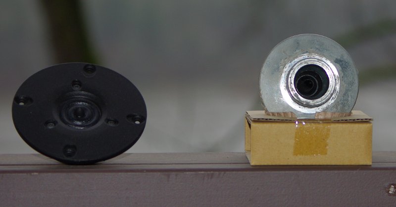
Here's where things get interesting! If you take the Celestion apart, you basically have a high efficiency dome tweeter with a very nice phase plug. It's difficult to tell in these pictures, but that's a 1.75" dome with a sophisticated phase plug mounted in front.
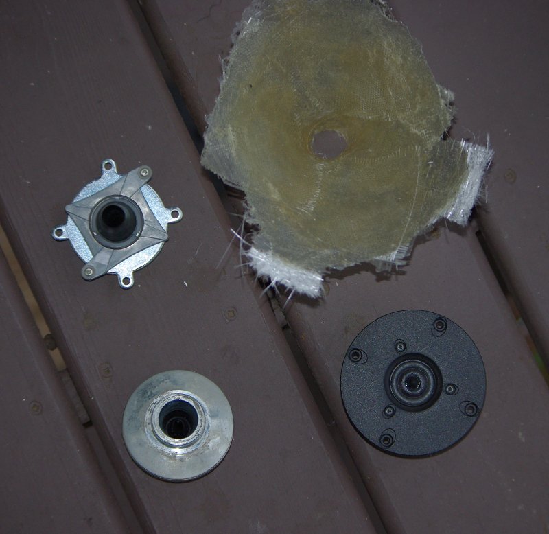
There are a number of other benefits as well. Brandon's measurements showed that the Celestion has lower distortion than the BMS. This is likely due to the larger diaphragm of the Celestion. Also, this waveguide design "pushes" the soundstage back by three or four inches.
This seems like an ideal solution. We reduce the depth of the waveguide, the overall size, and we still have very high efficiency. As a bonus, it *might* reduce high-order-modes. (Based on my understanding of HOMs, they're created by diffraction. By using a waveguide angle that is unchanging, we reduce diffraction. WIN-WIN.)
How about Focal ?
They make a line of tweeters with inverted domes and phase plugs, still a bit larger than what you're after but a good place to start.
HTH
Jorge
They make a line of tweeters with inverted domes and phase plugs, still a bit larger than what you're after but a good place to start.
HTH
Jorge
Over the weekend I hacked up the Celestion compression driver, and did various measurements. I also measured a direct radiator on a waveguide. In this post I'll cover the following:
Before diving into the measurements, I should cover my goals for the project. The whole reason that I want a small waveguide is to control early reflections. In the car I've found that reflections off the windshield and the side windows create audible colorations, reducing intelligibility and skewing the soundstage. But waveguides take up a lot of room. I'd like to use the existing curvature of the dash to extend the mouth of the waveguide. It doesn't take a very large waveguide to control directivity at high frequencies, but getting down to one or even two khz requires a VERY large device. By hacking up the compression driver, or using a conventional woofer, we can let the windshield and the dash do most of the work for us.
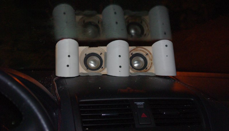
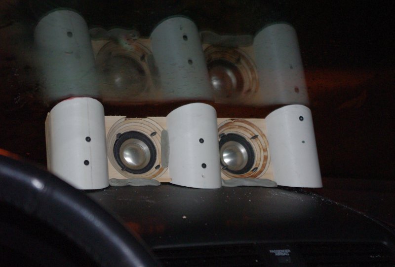
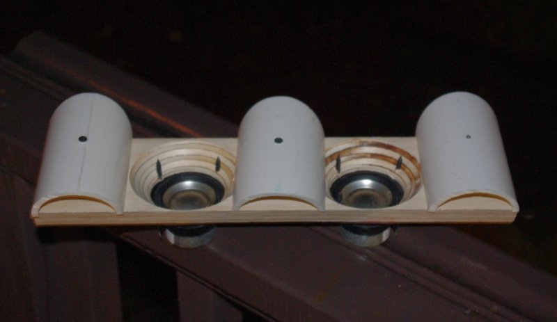
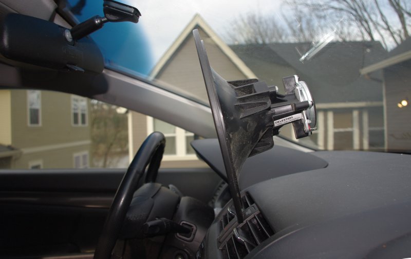
The first device that I tested uses a Peerless 830970 in a *very* shallow waveguide. I'm basically using it as a tweeter. The pics above are from my car. The device that I measured used a single Peerless woofer on a flat baffle, with a 1" roundover to reduce diffraction. The waveguide size is identical - about 3" wide and 3/4" deep.
The reason that I opted for this model instead of a conventional tweeter is that the larger diaphragm creates a narrower beam of sound than a conventional tweeter. The pic above is the published polar response, from Peerless. As a rule of thumb, loudspeakers beging to beam at wavelength that's equivalent to the piston's diameter. For the 830970, that means it will start to beam at 6750hz. But can we use a waveguide to control directivity down to two or three khz?
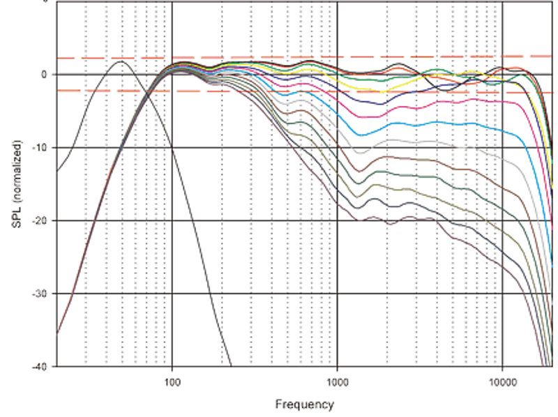 Here's the polar response of my reference, a set of Gedlee Summas. I measure on the same scale as Geddes, but my measurements are in 15 degree increments, his are in 7.5. We're both measuring from zero to ninety degrees. Note that I'm not trying to achieve flat response, I'm trying to achieve directivity control. So I don't care that the response is falling; that can be fixed electronically. Directivity can only be manipulated physically.
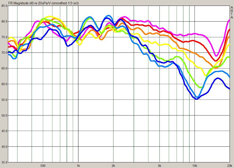 Theoretically, a waveguide that's 3" wide and 3/4" deep should control directivity down to 4500hz, with a beamwidth of ninety degrees. It appears that the Peerless waveguide performs a bit *better* than expected. The graph above shows a beamwidth of ninety degrees all the way down to 3khz! By 10khz the beam has narrowed to sixty degrees, which should reduce reflections even further. There's a dip at 16khz, which is also present in the literature from Peerless. This may be reduced via the use of a phase plug perhaps. All in all, I believe this is exceptionally good performance, particularly since the device costs less than ten dollars, including the woofer!
- How small can we make the waveguide?
- Which performed better - the direct radiator or the compression driver?
- What is the effect of termination (ie, roundover.)
Before diving into the measurements, I should cover my goals for the project. The whole reason that I want a small waveguide is to control early reflections. In the car I've found that reflections off the windshield and the side windows create audible colorations, reducing intelligibility and skewing the soundstage. But waveguides take up a lot of room. I'd like to use the existing curvature of the dash to extend the mouth of the waveguide. It doesn't take a very large waveguide to control directivity at high frequencies, but getting down to one or even two khz requires a VERY large device. By hacking up the compression driver, or using a conventional woofer, we can let the windshield and the dash do most of the work for us.
The first device that I tested uses a Peerless 830970 in a *very* shallow waveguide. I'm basically using it as a tweeter. The pics above are from my car. The device that I measured used a single Peerless woofer on a flat baffle, with a 1" roundover to reduce diffraction. The waveguide size is identical - about 3" wide and 3/4" deep.
An externally hosted image should be here but it was not working when we last tested it.
- Pros - very VERY inexpensive, small, easy to build, exceptionally good directivity considering the size.
- Cons - very low power handling, not as efficient as a compression driver, there's a dip at 16khz
Last edited:
Hi John
It's a performance versus size tradeoff across a continuum. Smaller and wider works better than smaller and narrower - the reasons for this are complicated so I'll just let it lie like that. Basically the narrower and more consistant you want the polar pattern to be the bigger the device has to get. You can trade off those two characteristics at will however. Many people find a very small waveguide arround a dome works great, and it will, as long as the angle is large, but narrowing that angle will cause a continued degradation in performance, unless the size gets larger. How much can you live with? Thats a design decision.
It's a performance versus size tradeoff across a continuum. Smaller and wider works better than smaller and narrower - the reasons for this are complicated so I'll just let it lie like that. Basically the narrower and more consistant you want the polar pattern to be the bigger the device has to get. You can trade off those two characteristics at will however. Many people find a very small waveguide arround a dome works great, and it will, as long as the angle is large, but narrowing that angle will cause a continued degradation in performance, unless the size gets larger. How much can you live with? Thats a design decision.
That nasty dip that moves down in frequency from 16k to 10k as you move off axis is similar to what I saw in simulating conical waveguides with no mouth termination. You might try smoothing out the exit of your waveguides and see if that helps. I've found building insulation styrofoam to be good to use for hacking around like this. You can shape it with wood working tools very quickly or use a hot wire.
Also if you normalize your response curves to the on-axis curve (or any other curve you pick), it can be a bit easier to see the device's directivity.
... is similar to what I saw in simulating conical waveguides with no mouth termination.
This could be two opposite things depending on what you mean by "no mouth termination" and I'm wondering which one.
1) Conical terminated no "radial flare" "mouth termination" or
2) Conical termination with no "sharp angled" "mouth termination".
I think that taken literally "no mouth termination" would be a device that was infinitely long such that "no termination" existed.
I would never use that phrase to describe an infinite device in the discussion of a real device...
I meant a conical horn that ends abruptly, ie, with no radius at the mouth to blend the conical section into a baffle or free space. In John's case I would specifically recommend ditching or modifying the PVC pipes that don't look like they are tangent to the conical section and fill in the corners at the mouth of the conical section so there is not an abrupt transition to the grill or dash.
I meant a conical horn that ends abruptly, ie, with no radius at the mouth to blend the conical section into a baffle or free space. In John's case I would specifically recommend ditching or modifying the PVC pipes that don't look like they are tangent to the conical section and fill in the corners at the mouth of the conical section so there is not an abrupt transition to the grill or dash.
I would never use that phrase to describe an infinite device in the discussion of a real device...
I meant a conical horn that ends abruptly, ie, with no radius at the mouth to blend the conical section into a baffle or free space. In John's case I would specifically recommend ditching or modifying the PVC pipes that don't look like they are tangent to the conical section and fill in the corners at the mouth of the conical section so there is not an abrupt transition to the grill or dash.
Yes, they should be designed to match the flare angle of the conical section. Otherwise they're HOM source discontinuities!
John,
First some observations...
You seem to be moving toward a center channel (given the current pictures and your posts on DIYMA).
You seem to be moving toward a more limited bandwidth (discussion of just using a center tweet on DIYMA)
Now some suggestions...
Build a 3.1 or 5.1 system (use DPL II or some other spatial processing)
Use a center channel unity horn using a combo of midranges and dome tweet. Dome jammed into the corner of the dash windshield juncture. Mids mounted below the dash and entering the bottom of the horn. Vertical edges of the horn to be terminated with a round-over and Horizontal edges blended into the windshield and dash.
The side channels are extremely high directivity gradually decreasing in directivity down until the low freq boundary of the center channel. Any midbass freqs (lower than the center channel high pass xover) are routed to these side channels. At this point the directivity has to be large enough to provide provide a phantom center image in the midbass freqs.
Now, this is the path that I am taking (have been for about 6 months - limited experimentation time). I think that it would address most of your goals...
Comments? Shortcomings?
I would never use that phrase to describe an infinite device in the discussion of a real device...
"No mouth termination" to me means no termination which implies no finite length.
Okay, I can see that, especially with regards to a simulation. That was just not in my mind at the time.
I always think of 'mouth termination' as what's at the mouth (of a real horn). So no termination to me means the horn just ends.
I always think of 'mouth termination' as what's at the mouth (of a real horn). So no termination to me means the horn just ends.
Okay, I can see that, especially with regards to a simulation. That was just not in my mind at the time.
I always think of 'mouth termination' as what's at the mouth (of a real horn). So no termination to me means the horn just ends.
My point was that I wasn't sure what you meant and being as they were 180 degree situations I didn't want to agree or disagree not knowing which was which.
- Status
- Not open for further replies.
- Home
- Loudspeakers
- Multi-Way
- Reducing Waveguide Size