Surely a few will still insist to try...
Someone would try gluing the voice coil to the pole piece if someone else said that "it might work" and then respond with "you never know till you try".
There is a trick you still deny to understand
Whether it works 100% or 50%, or not at all, is another matter
No, what you fail to understand is that I (and Geddes) have already described what is going on. It's a matter of trading bandwidth for effeciency. How it's accomplished is in principle needless to know. The acoustic lever is one way, the filtered passive radiator another, and coupled cavities yet another.
You don't magically get a higher average output from the same driver, no matter what method of those methods you use. If you do, congratulations on the Nobel price.
Last edited:
I (and Geddes) have already described what is going on.
Sorry, but thats a really funny one
It's a matter of trading bandwidth for effeciency. How it's accomplished is in principle needless to know. The acoustic lever is one way, the filtered passive radiator another, and coupled cavities yet another.
Its the reverse "no pain no gain"
Its true that there mostly are too many drawback
The big question is whether you can find a way to deal with the drawbacks, partly or completely
THAT has been said numerous times
There might be another way, into the pure passive radiator
You simply trap a difference compliance volume in the center rather than
around the outside edge. Shouldn't behave any different in theory. Pick up
any useless 18" ricer to try this for next to nothing, just to abuse as a PR...
How to trap the volume? Dixie cup over the vent hole in back??? Unless the
coil is rediculously huge, don't seem likely you could ever get near 2:1 lever.
Its cheap, but I question if the near unity front to back ratio of this lever
makes any sense?
Can you turn it around and trap part of the frontal surface area instead?
I don't have any real great ideas how that might be accomplished either...
Doesn't seem like its going to save any work over the original lever design.
In specific designs it can work and work well. I'm currently experimenting with a filtered passive radiator for use in my next Boominator design. Because bandwidth limitation and understanding of enviromental effects is one of the primary principles behind why the design works so well in practise, and looks so bad on paper when using conventional testing methods.
You simply trap a difference compliance volume in the center rather than around the outside edge.
Shouldn't behave any different in theory.
Nope, I just thought it would be much easier to build
Well, it does result in least possible "trapped air cavity volume"
Instead of looking at it like hornloading, maybe for simplicity resemble with BR
That is one calculated with peaked allignment
Its another of very few ways to get more output than the driver itself
Its something we usually really dont like
Its in the wrong place
And its "one note bass"
etc
1. question
Is this 1:2(?) conversion PR any different
2. question
Even if limited bandwidth, does it have slightly better bandwitdh than the peak of BR port
3. question
Does it overcome many of the problems of a peaked BR port, only some, or none
Attachments


Last edited:
I took the time to write out the differential eqs for the BP PR ans BP AL. Then I worked backward using the assumption that the radiating dis of the AL was the same size and had the same motion as the PR to see if any combination of parameters would yield the same motion of the active driver. The only way this can happen is if disk1 and disk2 of the AL are the same area. (also assumed the PR has same area front and back.
In any event, the AL will behave similarly to a PR but there is a difference in the details. I can't say which could potentially perform better. They are both forms of mechanical dampers and what they will radiate depends on how they are tuned.
In any event, the AL will behave similarly to a PR but there is a difference in the details. I can't say which could potentially perform better. They are both forms of mechanical dampers and what they will radiate depends on how they are tuned.
And its "one note bass"
etc
1. question
Is this 1:2(?) conversion PR any different
3. question
Does it overcome many of the problems of a peaked BR port, only some, or none
Two octaves isn't "one note", yes a 1:2 is different than a standard PR which is 1:1, and no it does not overcome any of the usual problems of BP designs, its just twice as efficient.
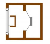
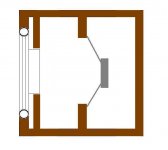
You left drawing won;t work as a lever and your right drawing would have a lever that is so stiff that it wouldn't work well either.
Tins' left drawing *IS* a lever. Just maybe not one of useful ratio.
Especially if we speak only of the area inside a typical el-cheapo
voicecoil being the main front to back difference.
I think he's crazy to want the smallest possible compliance volume.
Why?? This is only going to wind the springs all that much tighter.
And with a compensating mass to bring PR resonance back down,
significantly raise one-note Q'iness.
Geddes' trapped volume around the edge can potentially be both
larger and breath more freely into whatever additional volume can
be provided for that purpose.
1. Two octaves isn't "one note"
2. yes a 1:2 is different than a standard PR
3. You left drawing won;t work as a lever
and your right drawing would have a lever that is so stiff that it wouldn't work well either.
Have to correct a small misunderstanding
Im not arguing
And no, its not "acoustic-lever"
1. I did an assumption to compare with a high Q tuned ##BR##, as in ported
It too will have "gain"/peak with a small bandwidth
Of which I referred to as being one-note
And of no interest
On the other hand
Earl, you say the 2 octaves of a PR isnt one note, so its still a good answer
But ofcourse, it has the bandwidth of a PR, which is far better than the peak of high Q port
I should have known
Thanks
2. The question whether the 1:2 ratio PR would be different, it was related to whether it would be different from the peak of a high Q tunded BR with a peak(see 1.)
Well, its answered above
3. Both my drawings are excactly the same, just built different
I dont claim it to be just another "acoustic-lever"
On the contrary
This one is just a PR, but with a 1:2 ratio
You claim the 1:2 ratio PR wont work without a big chamber
But what happens if its small enough, and just what resembles that of the air behind a spider
If you look closer you will see its not a compressed chamber, but air can leak, as in ventilated spider
Its perfectly fine if it doesnt work
But I do not accept that it will not work just because its not a real "acoustic lever"
Attachments
Last edited:
Due to the 1:2 ratio, the PR moves twice as much
And maintains its size
But is it still controlled
Or maybe even better controlled
That seem to have been my misunderstanding
That 2x PR gives more output
But they really only just move half as much
Thats why I find this interesting
Need to go look at some calculating
To see what happens when the driver is loading a PR with half the usual size
hmm, seems ok with a small radiator
It would just move too much
But with greater outer surface, it needs less....
Last edited:
Hi,
FWIW the "acoustic lever" does not work as described and the claimed +6dB
efficiency is a mirage. Anything that claims to give something for nothing over
standard physics is inevitably incorrect in some detail (so see the patent...).
The fact that the lever does not work in principle (e.g. 1 : 100 area ratio)
means it does not work at all. For a 4:1 area ratio of main driver to the
smaller lever driver the idea excursion is multiplied by 4 is simply not true.
(As of course is not true for 16:1 causing x16 excursion or 100:1 causing x100).
It is only true in hydraulics.
The physics indicate all things being the same for +6dB you need a 4 times
bigger box, given the paucity of information in the patent, if you work out
appropriate volumes for the parts for it to work at all this is ~ true.
So you might as well have started off with a x4 box and a x2 diameter driver.
There is no real difference, unless you prefer to be swayed by claims
rather than hard physics, for the former case one presumes that your
physics are not really up to scratch, which is true for the majority.
If so, you then become the most easily manipulated by "claims".
The patent contains claims, hand-waving physics which are not true,
and some measurements, without remotely enough context to ascertain
the validity of the given measurements to the details of the claims.
The claim "+6dB" "better" is simply not true.
If you are still of the belief it works, consider a acoustic lever "cannon".
If we can get 6dB for nothing, the obvious thing to do is do it again, and
again, etc. until we hit similar acoustic limits to horn loaded drivers.
Or conversely thinking about it you could start off with a very small
driver and exploit this ability to massively expand its cababilities.
If you think this will work I suggest maybe your not that physics savvy.
It will work only if you expand the volumes of each added section such that
you end up building a hideously complicated horn loaded speaker, a simple
horn with one driver one would suggest might be somewhat easier.
(Or as said before a bigger box with a bigger driver to start off with,
FWIW : x4 box volume and x4 drivers = +6dB power handing and +6dB box
senstivity = +12dB maximum SPL compared to the one driver case.
This is also true of a x2 diameter similar driver in 4x the box volume).
The patent contains less rigour than is required in an undergraduates paper.
It is one thing simplifying the physics as long as its still essentially true,
but another using alleged "physics" to suit the details of your argument.
His patent stands on its own. Claims are irrelevant. Work it out for yourself.
If you cannot understand how it allegedly "works" do not build it, you will
not be learning anything, you will be taking it on trust or blind faith.
/sreten.
If you think this will work I suggest maybe your not that physics savvy.
/sreten.
I suggest you do a little more research before you embarass yourself further.
I suggest you do a little more research before you embarass yourself further.
I would very much like to see a SPL comparison between this and an equivalent bandpass box. Seems to me, the world's your oyster if this works as you claim, with pro apps beating a path to your door....
It might be interesting to have a head to head competition between an acoustic lever and a bandpass system. Dr. Geddes gets to spec the volume, bandpass and efficiency parameters, and gives it his best shot with his acoustic lever, as well as whomever designs and builds the bandpass system. No frequency shaping or xover components allowed. Sounds fair to me.")
In thinking about this I might have made one mistake, not sure. I did not mean to say that the efficiency increased by 6 dB, that wouldn't make sense since efficiency is in %. I did mean that the efficiency doubles and the output, in SPL, increases by 6 dB. The power of course only inceases by 3 dB, not 6.
There already has been a "Head to head" and it was published in SAE. I see no reason to do it again.
There already has been a "Head to head" and it was published in SAE. I see no reason to do it again.
I calculated an inner 8" PR to 25hz, and weight was quite fine, to make up fore a 12", both passives
I cant see it work any other way
If inner PR moves like an 8", but has the outside area of say 12", I cant see any other way than output will increase
Or slightly less power will be needed
Whether its significant, or worth the hazzle, or by how much, who knows
But I have room to play with 18" pro woofers, so I dont really care much
Though, my aim will never be SPL, so
Dont you guys ever want to have fun
Point missed
Last edited:
In thinking about this I might have made one mistake, not sure. I did not mean to say that the efficiency increased by 6 dB, that wouldn't make sense since efficiency is in %. I did mean that the efficiency doubles and the output, in SPL, increases by 6 dB. The power of course only inceases by 3 dB, not 6.
I worked through an analysis of the AL and PR system for a band pass design. I the looked at the case where the driver was fixed to see what would be the difference between an BP PR and a BP AL. I wanted the linear motion (excursion) of the PR to be the same as the AL. Thus, if the motion is the same the only differences would be in the radiated SPL which would depend on differences in radiating area. In order for the motion to be the same the following conditions must be met:
1) The area of the coupling disk of the AL (inner disk, A2) must be equal to the area of the PR, Apr.
2) The moving mass and mechanical resistance of the PR must be the same as those of the AL (the AL consisting of the double disk element and air volume between the disks).
3) The compliance of the PR suspension, Cpr, must equal the net compliance of the AL suspension and chamber compliance. I.E.,
1/Cpr = 1/Cal + (A3 –A2)^2/ Calc,
where Calc = Valc/(rho x c^2) is the compliance of the AL chamber. It should be obvious that with A2 = Apr, the compliance of the AL chamber can be altered by changing A3, the area of the radiating disk, and Valc, the volume of the AL chamber.
Given that these conditions are met the linear motion of the driver will be the same for both the PR and the AL systems, and the linear motion of the PR will be the same as that of the AL, independent of the area of the AL radiator, A3. That is both system will have identical transfer functions for the driver and radiating element. It follows that the radiated SPL of the AL will be 10 Log [(A3/Apr)^2] greater than the PR with the same BP response. The quantity (A3/Apr)^2 represents the increase in efficiency of the system as well since the electrical power input remains the same for both systems. Practical limitation would seem to arise from designing an AL with high enough Cal and/or large enough chamber volume, Valc. In the limit of very large Valc, Cpr = Cal. I have neglected the effects of the air mass load on the radiating surface as well as the radiation resistance. However, these can easily be compensated for by adjusting the Mms and Rms of the PR so as both the PR and AL have the same total moving mass and total resistance.
Earl, you know I would argue with you to the world end if I though differently, but in this case you need not apologies for being correct.
- Status
- This old topic is closed. If you want to reopen this topic, contact a moderator using the "Report Post" button.
- Home
- Loudspeakers
- Multi-Way
- Geddes on Acoustic Lever