I put this post here based on a reason that I see it as a loudspeaker system design issue, instead of discussion on amplifier's circuit.
A little background:
http://www.diyaudio.com/forums/tube...amp-tubes-how.html?highlight=transconductance
(In the first post of that thread, you may see THE background of this background.... )
That was the era I used tube amps for OB bass and thought about the current feedback concept. As usual, my action in building things is quite slow. I haven't done anything in that discussion yet and things went other direction.
And then I ran into http://www.diyaudio.com/forums/full-range/130679-t-bass-drive-ob-lf-drivers.html?highlight=t-bass which, for me, was an easier build than messing with (whole new) amps, and it delivered excellent results.
T-bass does one thing very well - drawing current from amp where most woofers can't do themselves around the low end resonant peak. Most amps are constant voltage, and designed for under-damped speakers (or simplied as resonant boxed speakers). When using those mid to low-Q woofs (designed for boxed) on open baffle, a lot of EQ is needed, not only for baffle loss, and for the too early roll off due to the low system Q.
Ordinary amp with a lot of EQ in front is trying to deliver more voltage gain on where the system impedance is high. But the impedance is often so high that the EQ can not catch up with. And the EQ is bringing some phase problem. Most people do this, I did it, too, but don't like it.
While T-bass circuit largely reduces the system impedance by the turn ratio of coupling transformer, thus much more current is delivered into the driver effectively. No (or less) EQ involved makes it superior in phase repsonse. I do love the bass sound from it. Very coherent, jumpy, tuneful, and delivered with a sense of effortless. (technically, the 'effortless' is a mistaken impression, because the amp is driving a hefty load as low as 1 Ohm.... )
Afterwards, by some post around here (I forget which, sorry), someone brought up Variable Amplifier Impedance, and it looked simple enough😀 (I'm mostly a speaker guy, then a tube guy. SS is somewhat difficult for me😱 ) OK, only 3 resistors are needed, or one of the original feedback resistor is kept, then I need only 2 per side😀
Mixed feedback with more 'current' content should be a very ideal way to work with low Q OB system. It 'automatically' delivers proper amount of current into the driver, which is a LOT more compared to the ordinary constant voltage amp - just what we need.
By the very simple (and doable) guideline in the article above by Mr. Rod Elliott, I modified my existed amp (a poor old Hafler) to have 20 Ohm output impedance.
How is this 20 Ohm determined? The measured Q's of my wooder on OB are Qes=0.31, Qms=5.25, Qts=0.29. I want a new system Q of 1.1, so I added extra 20 Ohm to the Re to have a new Qes of 1.25, and then a Qts of 1.1.
This mod on my amp was quite simple, with only one little different from the article - I need a cap to isolate DC in the feedback path.
Previouly, in my OB bass, T-bass circuit contributed about 10~12dB of 'EQ' ( 5~6dB boost on the low end and 5~6dB cut on the MB). And extra digital EQ in the upstream contributed another 7~8dB (+3 in the low end and -4~-5 around 80~120Hz... ). I think if I had tuned the T-bass better, or have a more capable amp, less EQ could do fine. Anyway, this low Q system needed 16~20dB of 'EQ' in total.
Now with a 20 Ohm Zo, it eliminates most of those EQ, now 2~3dB in total is enough to make it very flat 😀
How is the sound? Simply put, GREAT ! 😀 I can not compare it with the T-bass side by side, but I feel their sounds are almost the same -- low bass sounds are delivered effortlessly with coherent, jumpy, and tuneful qualities. ( a little bonus: the amp is now running much cooler, now it's really effortless 😀 )
I should've tried this much earlier. It's so elegant, no brute force is needed, and the result is so beautiful.
There might be a lot of mixed-up technical terms in my writing which were far from conscientious and thorough because of my excitement. Please correct me if something wrong.
🙂
Seems no interest, pity 🙁
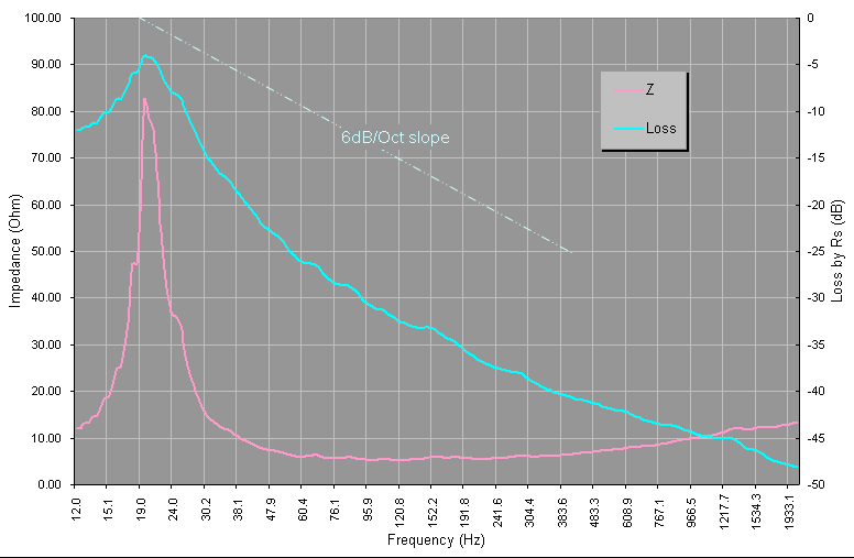
I made some spreadsheets and charts for visualizing the effects. The driver's (system's) impedance data were exported from the measurements by WT3. Then I added series R (output impedance, Zo) to simulate the 'loss' along the combo of this fixed series R and the measured impedance curves.
This is the current setting with 20 Ohm Zo, by calculation, system Q=1.1, and the deepest loss between 20Hz and MB is 10dB.
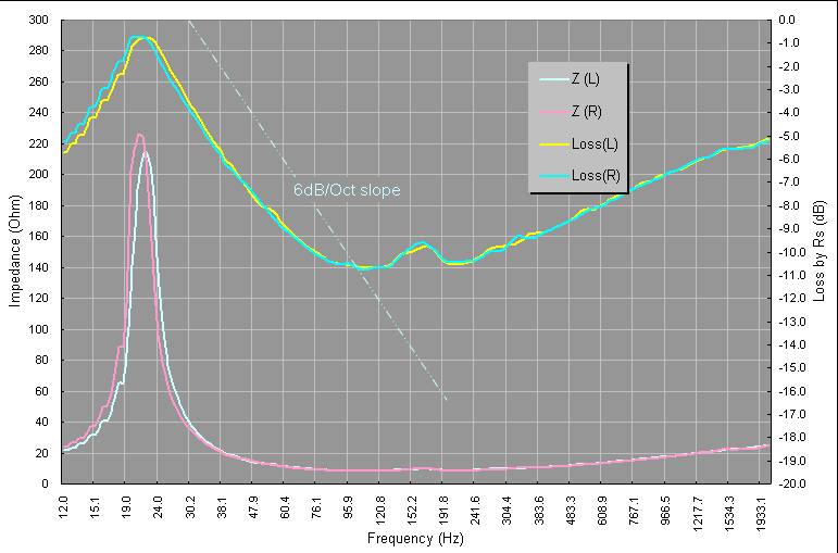
The real in room response needs extra 3dB or so to fulfill my taste, so maybe I'll increase the Zo to 32 Ohm, system Q=1.5, and the max loss comes to 12.5 ~ 12.7 dB, then it'll look like this:
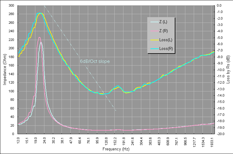
(a mysterious peak around 160Hz, appeared after the mod of phase plug... )
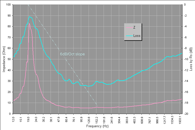
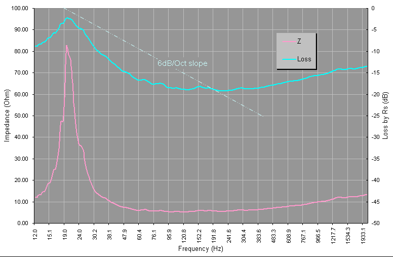
OTOH, I'm also working on the center 'sub', which accommodates 2 woofers in parallel, by the same 1.5 system Q and total loss of 12.5 dB, I'll add 24 Ohm Zo to the amp, it'll look like this:
Before that, I'll have to trace out the plate amp to find its feedback circuit...
I made some spreadsheets and charts for visualizing the effects. The driver's (system's) impedance data were exported from the measurements by WT3. Then I added series R (output impedance, Zo) to simulate the 'loss' along the combo of this fixed series R and the measured impedance curves.
This is the current setting with 20 Ohm Zo, by calculation, system Q=1.1, and the deepest loss between 20Hz and MB is 10dB.
The real in room response needs extra 3dB or so to fulfill my taste, so maybe I'll increase the Zo to 32 Ohm, system Q=1.5, and the max loss comes to 12.5 ~ 12.7 dB, then it'll look like this:
(a mysterious peak around 160Hz, appeared after the mod of phase plug... )
OTOH, I'm also working on the center 'sub', which accommodates 2 woofers in parallel, by the same 1.5 system Q and total loss of 12.5 dB, I'll add 24 Ohm Zo to the amp, it'll look like this:
Before that, I'll have to trace out the plate amp to find its feedback circuit...
Very interested here! Sorry I did not see the thread before. I will study it.
one note: I am surprised that you get a total Q of 0.29 on baffle. That's rather low for on baffle. What is the driver?
one note: I am surprised that you get a total Q of 0.29 on baffle. That's rather low for on baffle. What is the driver?
I tried this idea once and was very briefly pleased with the results. But the amp overheated and the output stage went up in flames.
Is there any consequence to this approach, when the loudspeaker (impedance) is disconnected? Does it affect amplifier stability, gain, phase margin etc?
Thanks,
Is there any consequence to this approach, when the loudspeaker (impedance) is disconnected? Does it affect amplifier stability, gain, phase margin etc?
Thanks,
Seems no interest, pity 🙁
Oh, there's interest all right.. some have suggested this and done this before..😉
Tube amps with higher output impedance react this way to a certain extent, but it's a matter of matching the resonant impdeance to the freq. response curve. (..one reason I often advocate a driver's resonance at around 70 Hz for this application in conjunction with an appropriate sized baffle.)
Suggestion (Isuzu commercial): GO FARTHER! 😀
In this respect consider that many don't want to give-up the tonality of their "reference" amp for an active setup.. OR don't want such a reactive setup broad-band. What's a designer to do? *Dual-VC's*. 😉 In fact the gain provided from the secondary VC IN CONJUNCTION with the primary will often off-set the need for any additional eq. depending on how you utilize a low-pass filter for the second VC.
Note that there are issues with headroom - so series connect your power output devices (..or parallel with higher output devices and add-in more resistance).
Last edited:
Hi panomaniac,
My woofers are Eminence Sigma Pro18 (older version with smaller magnet). Measured Q's in free air and on baffle were very close. Qes and Qms were slightly higher on baffle, but the differences were really small, like 0.30 vs 0.32 / 5.24 vs 5.29... and similar case in the fs -- 28 vs 29 Hz, or the likes. Maybe because the main baffle is very small - 55cm wide by 60cm high for a single 18".
In the case of center sub OB, the baffle is larger, and closer to the wall. It's measured fs dropped to high teens to low 20's. And the Qes even dropped to 0.17. Maybe I should measure it again to make sure....
😱
Quite the opposite in my case. 😕 My amp is running much cooler than before. Cooler than when it was not modified and driving a normal load, let alone the 1 Ohm load by the T-bass circuit afterwards.
The voltage of the power supply rails in the amp is +/- 53V or so, and the efficiency of the woofer is quite high, plus I usually listen quietly, so the head room for me should be OK.
I'm wondering, though, the current feedback and high Zo make the output current pretty much constant (related to input), so it would not rush up on the low impedance load like a low Z amp. While in the the mid to low bass frequencies where the impedance is so high (mostly dominated by resonant peak), current draw of both high and low Z amp would not be very high. So I thought the high Z amp must be clipped mainly by the limit of supply voltage, not by the current capability. No? 😕
OTOH, the woofer in free air or on OB is easily driven to exceed its Xmax. No matter driven by current or voltage sources, it needs only that much (little) power to reach Xmax. There shouldn't be any problem in amps I think.
BTW, my system is basically active 2-way. The amp mentioned above only works in the bass range.
Interesting😀 And it makes me think of this:
http://www.diyaudio.com/forums/multi-way/90804-large-midrange-ob-scott-g-41.html#post1955350
Wire two VC's in series, and shunt one of them with a large cap. Will it work?
But I'm thinking, even with (electrical) 1st order filter, the phase is still changed. So there'd be 2 forces which are not acting simultaneously. How can we deal with this?
My woofers are Eminence Sigma Pro18 (older version with smaller magnet). Measured Q's in free air and on baffle were very close. Qes and Qms were slightly higher on baffle, but the differences were really small, like 0.30 vs 0.32 / 5.24 vs 5.29... and similar case in the fs -- 28 vs 29 Hz, or the likes. Maybe because the main baffle is very small - 55cm wide by 60cm high for a single 18".
In the case of center sub OB, the baffle is larger, and closer to the wall. It's measured fs dropped to high teens to low 20's. And the Qes even dropped to 0.17. Maybe I should measure it again to make sure....
...
But the amp overheated and the output stage went up in flames.
😱
Quite the opposite in my case. 😕 My amp is running much cooler than before. Cooler than when it was not modified and driving a normal load, let alone the 1 Ohm load by the T-bass circuit afterwards.
The voltage of the power supply rails in the amp is +/- 53V or so, and the efficiency of the woofer is quite high, plus I usually listen quietly, so the head room for me should be OK.
I'm wondering, though, the current feedback and high Zo make the output current pretty much constant (related to input), so it would not rush up on the low impedance load like a low Z amp. While in the the mid to low bass frequencies where the impedance is so high (mostly dominated by resonant peak), current draw of both high and low Z amp would not be very high. So I thought the high Z amp must be clipped mainly by the limit of supply voltage, not by the current capability. No? 😕
OTOH, the woofer in free air or on OB is easily driven to exceed its Xmax. No matter driven by current or voltage sources, it needs only that much (little) power to reach Xmax. There shouldn't be any problem in amps I think.
BTW, my system is basically active 2-way. The amp mentioned above only works in the bass range.
ScottG said:In fact the gain provided from the secondary VC IN CONJUNCTION with the primary will often off-set the need for any additional eq. depending on how you utilize a low-pass filter for the second VC.
Interesting😀 And it makes me think of this:
http://www.diyaudio.com/forums/multi-way/90804-large-midrange-ob-scott-g-41.html#post1955350
Wire two VC's in series, and shunt one of them with a large cap. Will it work?
But I'm thinking, even with (electrical) 1st order filter, the phase is still changed. So there'd be 2 forces which are not acting simultaneously. How can we deal with this?
For those who are not familiar with SS amp circuits (like me), here I show you how I did the mods. We don't need to deal with the entire amp, only focus on the feedback circuit is enough (for this topic only, of course 😉 )
Here is a highly simplified circuit diagram of a typical SS amp (the upper one):
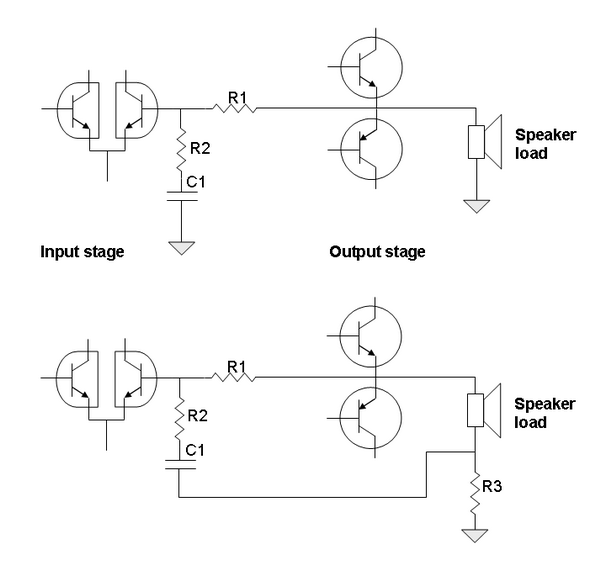
Trace it out from the output stage would be easier (components and copper traces are larger and simpler). You could find out a small resistor connected between output point (bus) and one leg of a tiny transistor. (Probably much nearer than you'd expect) At the same point it connects to the tiny transistor, there'd be another small resistor in series with a cap (mostly a low voltage 100uF electrolyte) and then to ground. These are the R1, R2, and C1 shown above.
Then according to the Figure 2 of this article:
Variable Amplifier Impedance
The following actions should be easy. Now the grounding point of the cap should be connected to the resistor in series with the load (R3 as shown above in the lower diagram) The calculation according to the article above is quite straight forward and you'll get the proper values of all the components by that simple equation.
Since the R2 might be changed, so you may also need to change the C1 accordingly to maintain a proper time constant.
Don't forget to re-adjust the EQ and damping of the system if any.
Have fun 😀
Here is a highly simplified circuit diagram of a typical SS amp (the upper one):
Trace it out from the output stage would be easier (components and copper traces are larger and simpler). You could find out a small resistor connected between output point (bus) and one leg of a tiny transistor. (Probably much nearer than you'd expect) At the same point it connects to the tiny transistor, there'd be another small resistor in series with a cap (mostly a low voltage 100uF electrolyte) and then to ground. These are the R1, R2, and C1 shown above.
Then according to the Figure 2 of this article:
Variable Amplifier Impedance
The following actions should be easy. Now the grounding point of the cap should be connected to the resistor in series with the load (R3 as shown above in the lower diagram) The calculation according to the article above is quite straight forward and you'll get the proper values of all the components by that simple equation.
Since the R2 might be changed, so you may also need to change the C1 accordingly to maintain a proper time constant.
Don't forget to re-adjust the EQ and damping of the system if any.
Have fun 😀
Last edited:
Interesting😀 And it makes me think of this:
http://www.diyaudio.com/forums/multi-way/90804-large-midrange-ob-scott-g-41.html#post1955350
Wire two VC's in series, and shunt one of them with a large cap. Will it work?
But I'm thinking, even with (electrical) 1st order filter, the phase is still changed. So there'd be 2 forces which are not acting simultaneously. How can we deal with this?
A 1st order electrical (passive) on the INPUT of the amp, represents minimum excess phase (..or additional group delay).
Do NOT wire the VC's together, instead one VC should be part of the loudspeaker driven from your "reference" amp, the other should be driven (actively) with an additional "beefier" amplifier with the impedance correction on the output and the passive 1st order on the input. (..your preamp should be "split-out" to each of the respective amplifiers, the "reference" amp and the impedance compensation amp.)
Look to the 12 inch DVC drivers from Pioneer (..they have foam surrounds that help with eff.). Decent eff. on *EACH* VC of around 91-92 db, and most notably a LOW FS. (..or rather a relatively low FS.) MCM electronics also has a rubber surround version that is similar. Both are cheap and should be used in "quads" per side/channel (with each driver's VC series/parallel connected to the next driver (of 4) for a net 6-8 ohm load for each of the 2 VC connections).
Last edited:
Yep, that's it.Maybe because the main baffle is very small - 55cm wide by 60cm high for a single 18".
--
This circuit does look like a very nice idea for OB. You can dial in the system Q you want.
Looking over the circuit brings some questions to mind.
1: A constant current amp is going to be just that, CC. So what happens at the upper end of the woofer's range? The impedance is rising, so the CC amp is going to supply more voltage to keep the current constant. Will that tend to flatten the woofer response, or even cause a rising response?
2: Looking at the schematic in the article the feedback resistor at the speaker (R3 in your diagram) immediately made me think "inductor DCR." So what if this resistor were an inductor? It would be acting as a low pass filter on the woofer, but what would happen to the voltage divider (woofer+R3) that drives the feedback? It's going to change with frequency. Could it be put to good use?
I'm sure many people have thought about this before. So what are the answers?
.
...
one VC should be part of the loudspeaker driven from your "reference" amp, the other should be driven (actively) with an additional "beefier" amplifier with the impedance correction on the output and the passive 1st order on the input.
...
😀 That's what I'm doing with my system! It's just not dual VC in one woofer. Instead, I use separate woofers driven avtively with different LP points. (similar to those 2.5way or 3.5way systems)
Last night I tried the modified plate amp with 24 Ohm Zo. It's driving my OB center sub (with 2 identical woofers as the main channels). The 24 Ohm Zo yields a 1.5 system Q. It seems quite high but actually adequate (by ears) for such a subwoofer working on the very bottom octave (20-40Hz).
Working together with the main channels, now the whole system needs ZERO EQ on the bass range! 😎
The total Q of the main channels is tuned to 1.1, and 1.5 for the sub. But the whole system is not boomy at all. The sub adds a tad of (but also significant) weight and authority to the foundation. The senses, although very small, of vibrations or 'puffs' by the air flows in the sounds adds quite an awsome effect. And it doesn't need high SPL to enjoy the bursts of bass notes which are coherent with the whole spectrum.
...
1: A constant current amp is going to be just that, CC. So what happens at the upper end of the woofer's range? ...
2: Looking at the schematic in the article the feedback resistor at the speaker (R3 in your diagram) immediately made me think "inductor DCR." So what if this resistor were an inductor? ....
According to the article by Nelson Pass (who made a CC amp), most speakers don't like 'pure' CC (infinite Zo). Instead, in his experiments, 47 Ohm works well with most high sensitivity fullrangers. (I use 20-some Ohm on my woofers.)
I think, as a whole, it's a mixed matter of system Q and intrinsic (or system) frequency response.
About the upper end, I have no experiences. Again, in the article by Nelson Pass, he used some LRC networks in parallel with speakers to tune the load impedance, thus the response.
And using an inductor as the current feedback R3 is so interesting. Yes it'll be a LP filter and maybe good for pure bass (subs) usage. Or cancelling out the rising impedance of some loads by carefully chosen inductor (or a LR combinations). I think it'd have same or similar phase behavior as (any other forms of) 1st order LP filters. Let's wait and see if anyone will try...
After careful listening of these days, I re-adjusted the system Q of the center sub from 1.5 to 1.1. The previous 1.5 was too much for about half of my recording collections.
And I also found a little drawback of this setup. I heard some buzz, very quiet but audible. As I often listen quietly so I hear it from time to time. The woofers and speaker cables are now part of the feedback cirtcuit. I suspect the loops pickup some power line noises and feed it back into the amps. Not sure yet. My speaker cables are all twisted pairs, maybe not enough? I'll try shielded cable to see if it helps.
It'd be much appreciated if someone might share his/her experiences on this 🙂
OK, I think I'm still alone here....
Anyway, the other day I tried both shielded speaker cables and choke as current feedback element.
No luck in the buzz noise by shielded cables 🙁 Still buzzing. And I can't tell if any improvement. (The shielding was made of copper foil and I connected one end of it to the ground point of the plate amp. )
And then I tried an iron core choke (2.6 mH / 0.16 Ohm) as the current feedback element in the plate amp for sub. The DCR is identical to the previous resistor, so the feedback is the same at DC. Above that, the feedback goes more and more, i.e., the gain goes less and less. So now the plate amp is working with this super LP filter as the response declines from DC. (Oh! uh... maybe not. There's another RC combo along the path to shunt the DC... )
So in the audio band, I got less gain. Luckily there's surplus gain in the original design, so I just turned up the level and done.
The inductor feedback path yeild another 6dB/oct LP filter right from DC, so now its output response is different from previous status even though I brough back the gain. If I matched the level at 40Hz, than I got additional 6dB at 20Hz. If I matched it at 20Hz, then it's 6dB down at 40 - barely works most of the time.
My final setting was, maybe, somewhere in between. And it measured FLAT to 20Hz ! 😀 Another bonus is, the buzz noise is gone! 😀
Before I made this mod, I somewhat worried about the response would be too 'steep' and similar to the previous high Q setting. Fortunately it turned out very good. Better control than the previous high Q setting and VERY extended. The only drawback is the plate amp and woofers have to work harder to deliver that bass. The excursion of the woofers on sub is now larger than that of the main channels when there're bottom octave contents in the materials. And the plate amp is working slightly warmer.
The choke can not be used directly in my main channels since the response is only good for sub. I need midbass range in main channels. So I'll need different inductance or maybe some kind of LC network... And I have to find a way to sucure the chokes since the Hafler for main channels is very small and no way can it accomondate those bulky chokes...
Hey - great work! Good to hear that the inductor trick worked so well. Other than more low end, can you hear any other changes? Did it seem to change the Q or dry/wet sound of the bass?
I am not surprised that you came back from a 1.5Q. That must have been a little "sloppy" on a lot of music. Keep up the good work!
I am not surprised that you came back from a 1.5Q. That must have been a little "sloppy" on a lot of music. Keep up the good work!
To be honest, it's hard to clearly describe the changes in sound quality. After all now the sub is working in an even narrower band, maybe less than 1 octave! The initial impression was almost identical quality as the previous Q=1.1 setting, and then adding the 1st order LP filter to the response curve.
I have no precise measurement curves to show, but I guess the shapes of this curve and that of Q=1.5 should be very similar -- a relatively narrow flat top hump at the bottom octave. However they are somewhat different to my ears (and body😀 ). The one with inductor dives deeper and stops quicker. Additional 6dB/oct slope makes less midbass, maybe this helps a little in systme integration. General speaking, it's an improvement! Thanks for the brilliant idea, pano🙂
I have no precise measurement curves to show, but I guess the shapes of this curve and that of Q=1.5 should be very similar -- a relatively narrow flat top hump at the bottom octave. However they are somewhat different to my ears (and body😀 ). The one with inductor dives deeper and stops quicker. Additional 6dB/oct slope makes less midbass, maybe this helps a little in systme integration. General speaking, it's an improvement! Thanks for the brilliant idea, pano🙂
Hi CLS!
Nice work. A few years ago I have also tried the Variable amp trick from Rod's page. I tried in on my LM 3886 gainclone. While there was more bass, there were also some strange clicks...and puff...one channel was gone with 25+ v dc on the output. Luckily I was using a cheap speaker for testing, connected with clip leads, so I managed to disonncect it before the cone launched itself...
Nowadays, I am using OB's, biamped. Visaton B200 in the highs, Eminence Beta 15 in the lows. Zen V9 is running the B200's, and a SS Sony TA-N 511 is running the Beta 15, via T-bass. So far I am mostly happy with the setup, except that the Sony is running warm, and on loud pasages, protection kicks-in and disconnects the output, so I can't play it very loud, but 95% of the time I don't need to. (I do need to do some more tweaks, and may ask Graham in T-bass thread).
On the other hand, the idea of increasing the amp impedance is appealling, provide that I don't burn the amp and the speakers...
Regards,
Vix
Hi,
Did you include that DC blocking cap in the feedback loop? C1 in my #7 post.
In my own mods, at first I followed that article by Mr. Rod Elliott directly and found about 4.x DC on the output. Luckily that was on my desk with dumy load. Then I added that DC blocking cap and it's fine, except that little buzz noise I haven't figured out yet.
My Hafler SE120 is running cool with no other problem at all, even on some loud passages, it's still rock solid. (It's solid state, after all😀). For an almost 20 years old and tortured little amp, it's just amazing! And the later Dayton plate amp for my sub is also very durable and easygoing.
Last edited:
Hi,
Did you include that DC blocking cap in the feedback loop? C1 in my #7 post.
Hm...I can't tell right now, but I remember that it didn't fail immediately; it was working one minute maybe, and there was some DC offset, but later it blew up, so I don't know whether it was due to the (missing) capacitor, or something else. I'd have tried this on Sony, but as I have no schematic, I was a bit reluctant to fiddle with it...
I may come back to it eventually, and try this mod once more, make sure that the cap is there, and see what happens...
Thanks for the brilliant idea, pano
You're very welcome! Glad you tried it.
Yes, I would imagine that it would be hard to judge the Q change with the large change in FR.
This is a fun circuit to try, I'll have to figure out if I can graft it into one of my amps. Thanks CLS.
Well, last night I just found out something not so good in the inductor setting. It seems this choke and that coupling cap form an LC resonator with a frequency <1Hz.
When power on and off, there're huge movements on the cones, maybe 2cm peak to peak at the max. It's slightly 'calmer' when power on and more violent when off. Less than one cycle when on and maybe 1 and a half cycles when off. Those are different from regular 'pops' because the movements are very slow thus no sounds. That kind of excursions are quite scary, though.
No damage up to now. And it was working well. I think I'll parallel the choke with a resistor to damp this on-off excitement...
I made some spreadsheets and charts to visualize the effects of inductor as current feedback element:
This is the previously mentioned choke with 2.6 mH, 0.16 Ohm DCR in the position of "R3":
(note that the scale is very different from the ones I posted previously)
The output impedance is changing with frequency and quite high. It's 35.94 Ohm @ 12Hz, rising up with frequency, and skyrocketing to 3395 Ohm @ 2kHz. (I didn't calculate those above... )
And the following is adding a 0.5 Ohm in parallel with that choke:
With the damping resistor, the Zo of amp is changing not so severely. 21 Ohm @ 12Hz to 50 Ohm @ 2kHz. (Seems a good compromise... )
The inductance is less dominating when the parallel resistor get smaller. I can't figure out the sweet spot now, just fiddling with these numbers...
I'll give it a try tonight.
- Status
- Not open for further replies.
- Home
- Loudspeakers
- Multi-Way
- Low Q Woofer in OB with High Zo Amp