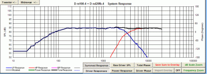
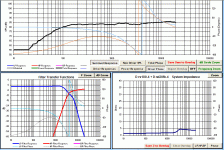
I've been using Passive Crossover Designer and have managed to get a fairly flat response. (Dayton rs100-4 and nd20fb-4)
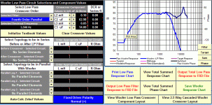
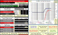
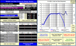
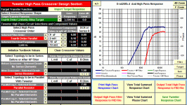
Woofer crossed over at 3500Hz, tweeter at 3300Hz. (With 4dB attenuator)
Does this response look ok? Please request more details if needed.
One more question: should I use Zaph's FR graphs or the Dayton ones?
Woofer crossed over at 3500Hz, tweeter at 3300Hz. (With 4dB attenuator)
Does this response look ok? Please request more details if needed.
One more question: should I use Zaph's FR graphs or the Dayton ones?
Attachments
The response looks OK to me.
But: the values you chose don't exist, try first to put "regular" values. As an exception, the value of an inductor can be easily modified (only to a lower value).
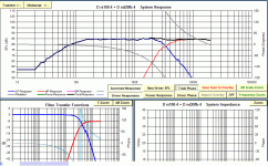
Second, the total phase is IMHO meaningless. If you would like to have the drivers in phase look at "Driver Phase": the phase of the drivers should be very similar in the xo region.
Third, I don't see any graph in the System Impedance chart. Are you sure to have loaded an impedance file for the drivers? If not, the program will assume IIRC a constant 8 Ohm, and of course the calculations will not be correct.
Last, I would use the Zaph graphs for SPL. For impedance I would rely on manufacture's one, as usually the Zaph ones are too compressed.
Ralf
I tried with "normal" values from PE, and traced the .zma files from the Dayton impedance graph. I'll be happy to settle with this response if there are no underlying problems  .
.
If there are any, please let me know .
.
If there are any, please let me know
Attachments
Last edited:
(Disclaimer: I'm not and expert, but I successfully done what I will speak about)
I'm still not convinced about the impedance. I mean, the woofer impedance and also the summed one, should have a peak of some 15 Ohm around Fs. Are you sure to have entered a correct zma file for the woofer? Besides that, the total impedance plotted is really low, I fear to connect such a load to my amplifier.
Another thing that I see now, but should have seen also before: you didn't compensate for baffle step. In case you are not aware of this effect, in a few words, depending on the width of the baffle frequencies lower than a certain value wrap around the speaker so you lose half of the sound. That means a 6 dB loss. The effect is not abrupt, but goes smoothly in the range 100 - 1000 Hz. See for example this transfer function: ZMV5.
What you should do is to compensate at least partially for this effect. If you don't the bass will be 6 dB lower that high midrange and treble. You can see where this effect occurs using some other software like edge, or some excel spreadsheet from the FRD consortium (BSD and FRC). For guidance on how to use BDS and FRC look here. What I can add is that in order to successfully use those programs you have to know the baffle used in the manufacture's measure. This is why I prefer to use the Zaph's ones, because those are done on an infinite baffle.
Ralf
- Status
- This old topic is closed. If you want to reopen this topic, contact a moderator using the "Report Post" button.
