Go easy on me...I am new to this! 😛
So, here is my first journey through the world of speaker building. A friend of mine built some back in college, and the sound quality obtained at the price he paid (or didn't pay, rather) blew me away (especially so, since I was in college & broke). Now, being out of college for a while, having a little money, and living in a reasonable proximity to my father's wood/machine shop I decided it was time to play around. The main criteria was size...I wanted these to fit reasonably on my 60" x 28" desk, next to my PC monitor & also be around sitting ear-height. I decided upon a WxHxD of 8"x16"x10", which according to WinISD, would provide a -3dB point at 46Hz in a ported box with a reasonable port length using the selected driver.
The drivers I went with were AuraSound NS4-255-8F's form Madisound, which had good T-S parameter documentation & the best bass response of any of the lower-priced 4" full-range ones. Tweeters were AuraSound NT1-208-8D's which were cost-effective, and would be easy to integrate with the 4" drivers to pick up where they left off.
4" Full-Ranges: http://www.madisound.com/catalog/product_info.php?cPath=45_241_309&products_id=8471
Tweeters: http://www.madisound.com/catalog/product_info.php?cPath=45_229_250&products_id=1767
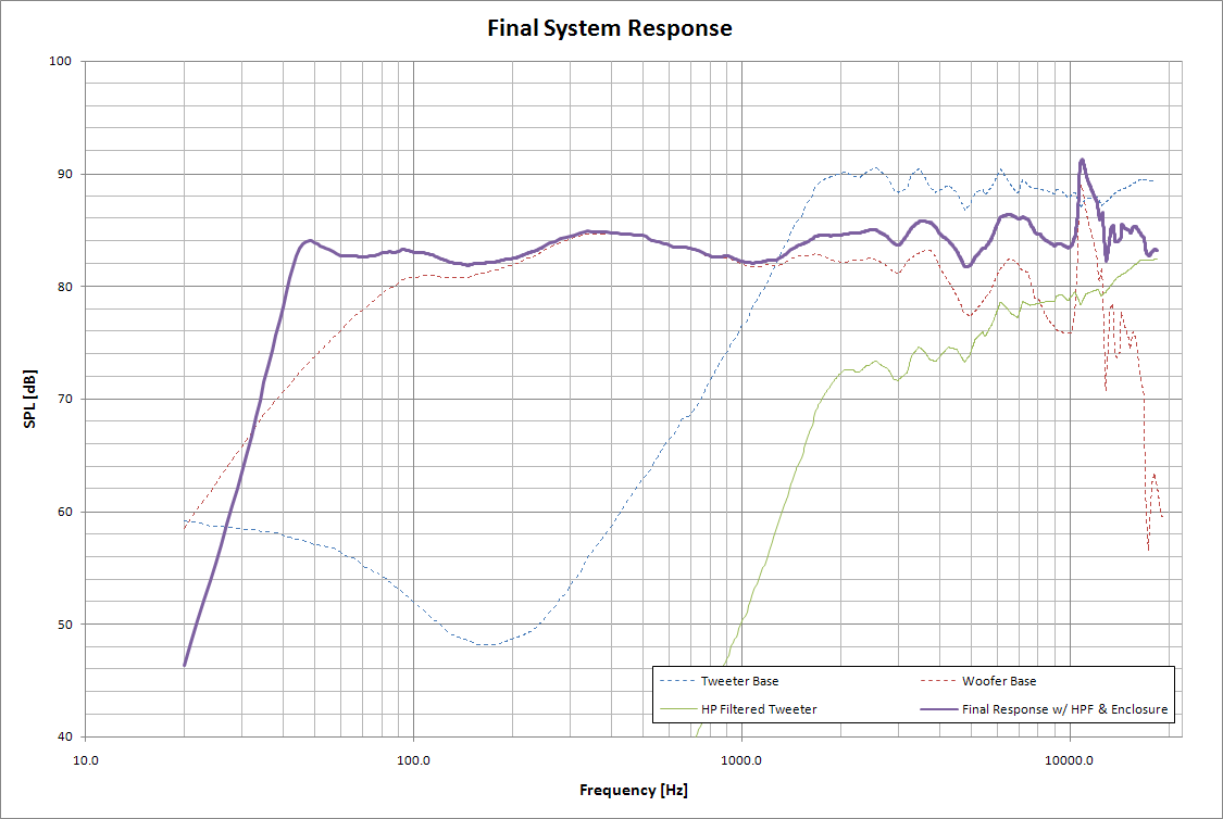
After iterating through WinISD and a very overkill Excel sheet to calculate the actual internal volume (accounting for port volume, driver volume, driver cutout volume, sound deadening, etc) I made another overkill Excel sheet to simulate the pair of speakers' response with a 1st order filter on the tweeter. See the plot below for the response using a 2.2uF cap & 8 Ohm resistor in series with the tweeter (the resistor is to lower the tweeter's sensitivity by 6dB since it is more efficient than the driver, and its impedance actually IS ~8 Ohms for all frequencies). I have also accounted for the effects of the enclosure on the woofer. The reason I am going so cheap on the passive XO stuff is because I fully intend to go active & bi-amp these. Actually, I'll probably make a sub & tri-amp it all.
The ACTUAL documented impedance of the tweeter was used for the XO calculations here....digitized from the data sheet. I wrote a custom VB app to interpolate between the digitized points (SPL & impedance values for both speakers at the same frequencies) so that I would have nice conformity between the 2 speakers should I choose to go passive with both. The response looks pretty darn flat, and it certainly sounds that way (sadly, my ears are not calibrated, to that claim is purely subjective at best). At any rate, the flat response still drops off about 20Hz too soon on the low end. I am planning on building a subwoofer to go with these. They sound great for being 4" drivers, but I want more bass now (many months later).
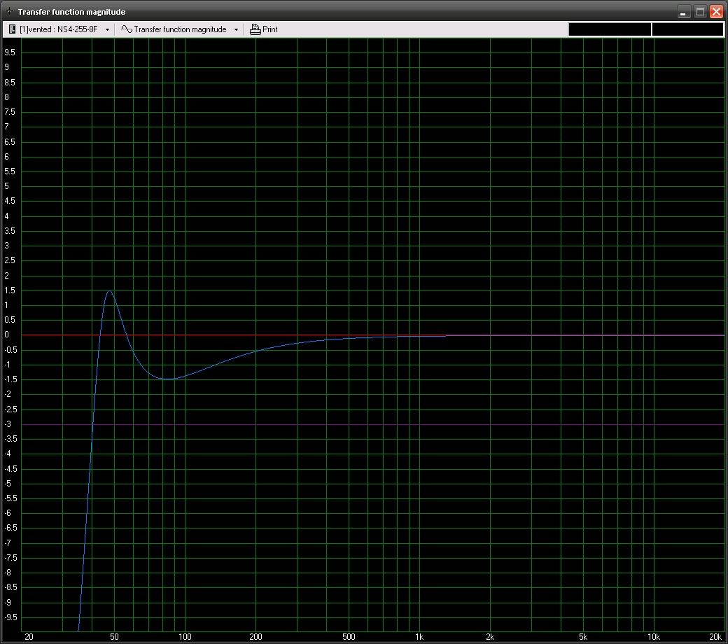
The transfer function in WinISD was calculated ot be as follows (I decided that +/- 1.5dB was acceptable deviation):
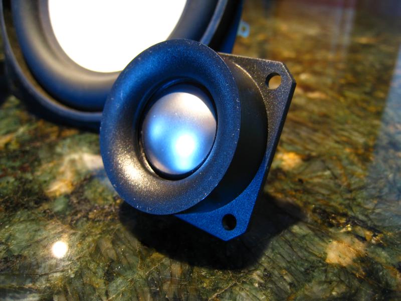
Here are the tweeters.
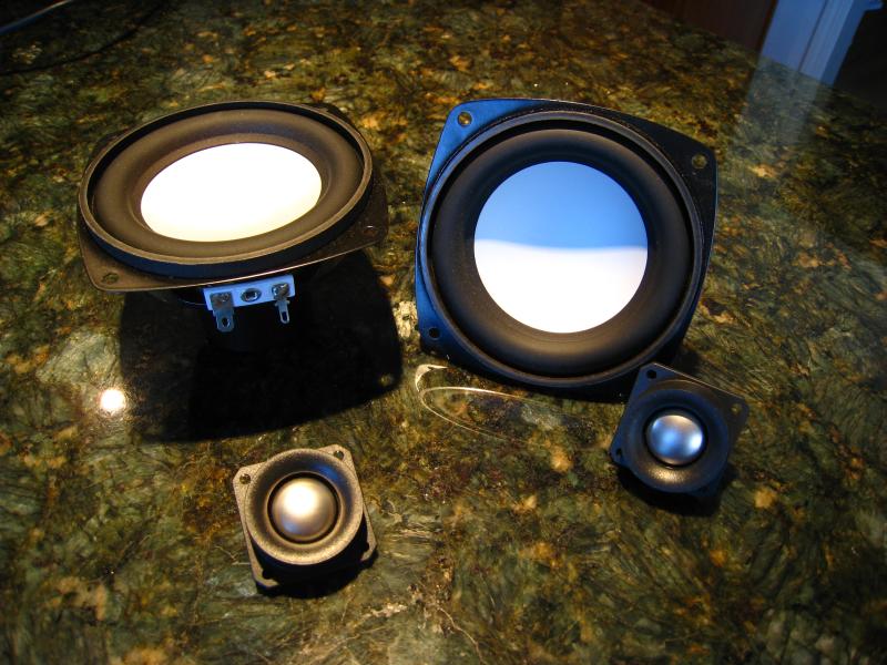
Tweeters with drivers.
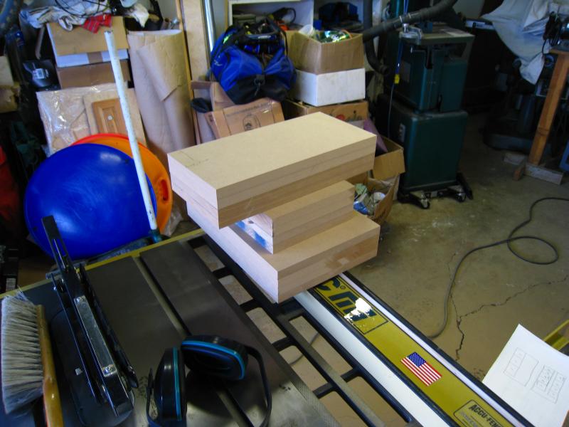
Supplies, awaiting assembly. I ended up using Gorilla Glue instead of regular wood glue.

The rough cuts for the panels.
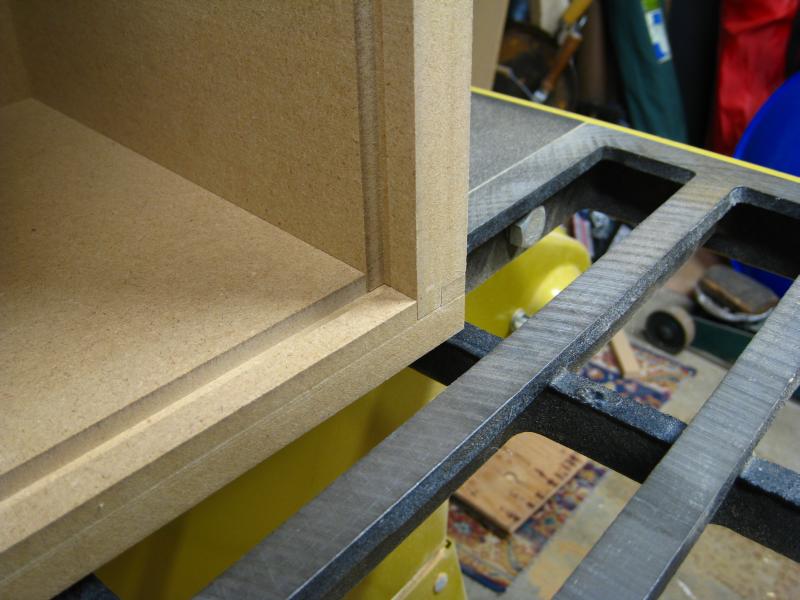
Test-fitting the pieces after routing rabbit-grooves into them. I did it such that they would all interlock and be self-standing before gluing.
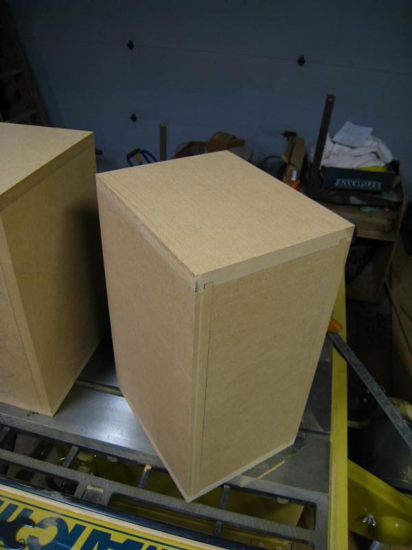
The grooves.
So, here is my first journey through the world of speaker building. A friend of mine built some back in college, and the sound quality obtained at the price he paid (or didn't pay, rather) blew me away (especially so, since I was in college & broke). Now, being out of college for a while, having a little money, and living in a reasonable proximity to my father's wood/machine shop I decided it was time to play around. The main criteria was size...I wanted these to fit reasonably on my 60" x 28" desk, next to my PC monitor & also be around sitting ear-height. I decided upon a WxHxD of 8"x16"x10", which according to WinISD, would provide a -3dB point at 46Hz in a ported box with a reasonable port length using the selected driver.
The drivers I went with were AuraSound NS4-255-8F's form Madisound, which had good T-S parameter documentation & the best bass response of any of the lower-priced 4" full-range ones. Tweeters were AuraSound NT1-208-8D's which were cost-effective, and would be easy to integrate with the 4" drivers to pick up where they left off.
4" Full-Ranges: http://www.madisound.com/catalog/product_info.php?cPath=45_241_309&products_id=8471
Tweeters: http://www.madisound.com/catalog/product_info.php?cPath=45_229_250&products_id=1767
After iterating through WinISD and a very overkill Excel sheet to calculate the actual internal volume (accounting for port volume, driver volume, driver cutout volume, sound deadening, etc) I made another overkill Excel sheet to simulate the pair of speakers' response with a 1st order filter on the tweeter. See the plot below for the response using a 2.2uF cap & 8 Ohm resistor in series with the tweeter (the resistor is to lower the tweeter's sensitivity by 6dB since it is more efficient than the driver, and its impedance actually IS ~8 Ohms for all frequencies). I have also accounted for the effects of the enclosure on the woofer. The reason I am going so cheap on the passive XO stuff is because I fully intend to go active & bi-amp these. Actually, I'll probably make a sub & tri-amp it all.
The ACTUAL documented impedance of the tweeter was used for the XO calculations here....digitized from the data sheet. I wrote a custom VB app to interpolate between the digitized points (SPL & impedance values for both speakers at the same frequencies) so that I would have nice conformity between the 2 speakers should I choose to go passive with both. The response looks pretty darn flat, and it certainly sounds that way (sadly, my ears are not calibrated, to that claim is purely subjective at best). At any rate, the flat response still drops off about 20Hz too soon on the low end. I am planning on building a subwoofer to go with these. They sound great for being 4" drivers, but I want more bass now (many months later).
The transfer function in WinISD was calculated ot be as follows (I decided that +/- 1.5dB was acceptable deviation):
Here are the tweeters.
Tweeters with drivers.
Supplies, awaiting assembly. I ended up using Gorilla Glue instead of regular wood glue.
The rough cuts for the panels.
Test-fitting the pieces after routing rabbit-grooves into them. I did it such that they would all interlock and be self-standing before gluing.
The grooves.
Last edited:
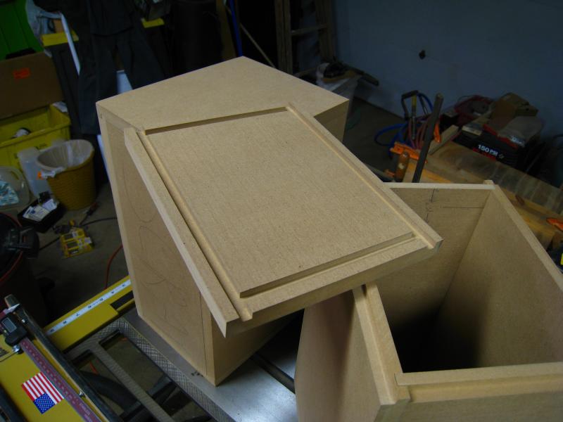
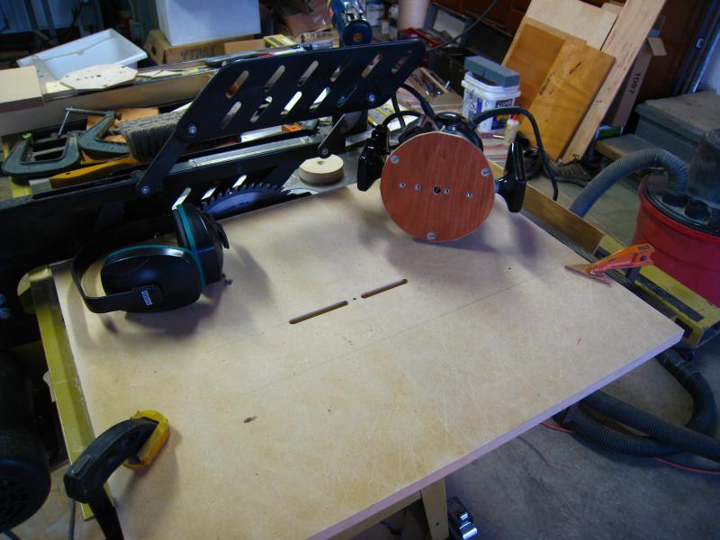
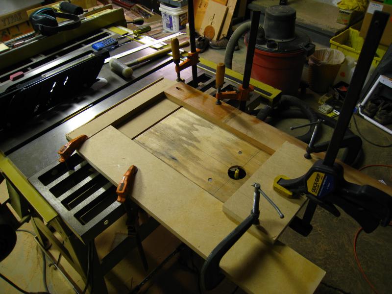
Here is one of the many router jigs I came up with.
Just a gratuitous shot of the fitting. I was pleased with it, considering this is the first woodworking project I have embarked upon.
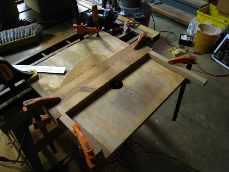
I also had to come up with a custom rig for routing the circular holes. This worked out very well.
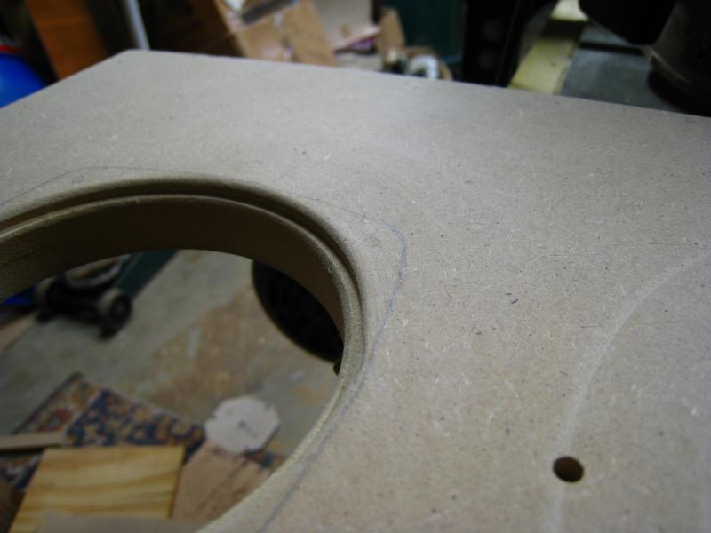
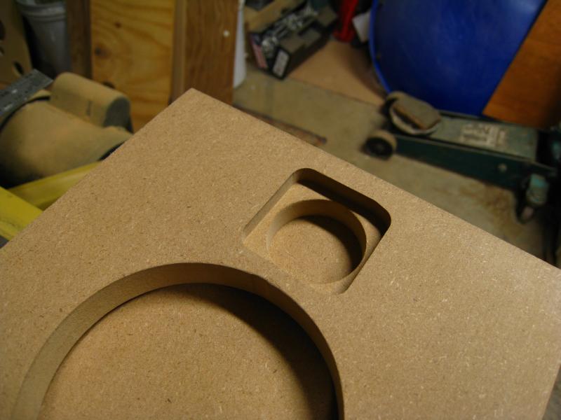
I used a recess on the driver hole to better conform to its profile, which I would later put closed-cell foam strips on for sealing.
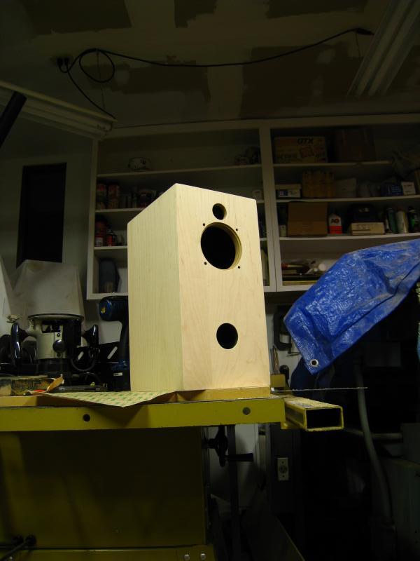
Here are the front faces.
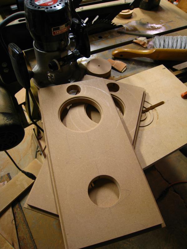
Test-fitted with all the major cuts.
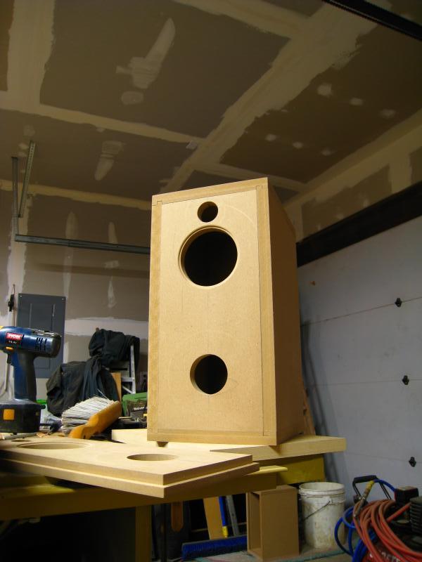
The trickiest jig was the one for the rear-mounted tweeter recess. It worked, though.
It is not quite perfect, but it is certainly good enough.
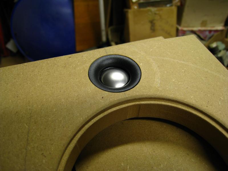
Yup. the tweeter fits in the spot, is flush, and there is no horrendous gap around it.
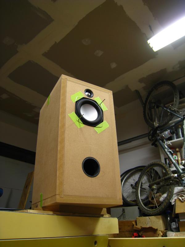
More test fitting, now with drivers, tweeters & green tape!
Just a gratuitous shot of the fitting. I was pleased with it, considering this is the first woodworking project I have embarked upon.
I also had to come up with a custom rig for routing the circular holes. This worked out very well.
I used a recess on the driver hole to better conform to its profile, which I would later put closed-cell foam strips on for sealing.
Here are the front faces.
Test-fitted with all the major cuts.
The trickiest jig was the one for the rear-mounted tweeter recess. It worked, though.
It is not quite perfect, but it is certainly good enough.
Yup. the tweeter fits in the spot, is flush, and there is no horrendous gap around it.
More test fitting, now with drivers, tweeters & green tape!
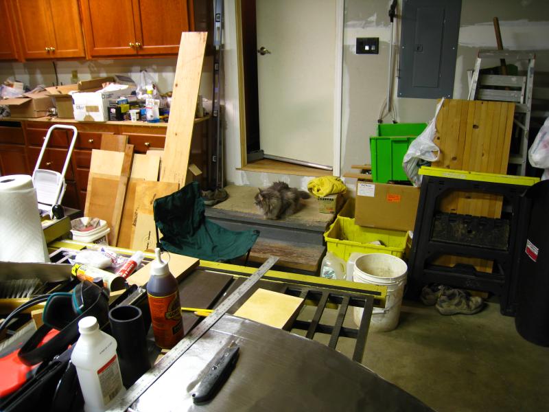
My trusty helper...watching...waiting...(for food)
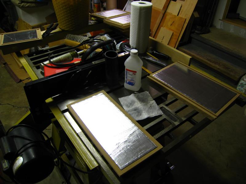
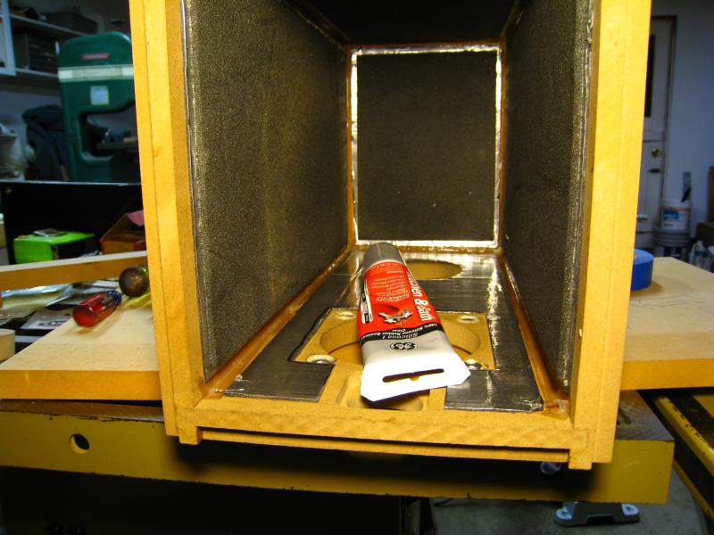
I had some butyl-rubber sound deadening with 6-mil aluminum foil bonded to it left over from a car project. I used it on all interior surfaces (front panels were done later).

I also left 0.25" around the edges for the silicone caulking I was going to seal the seams with.
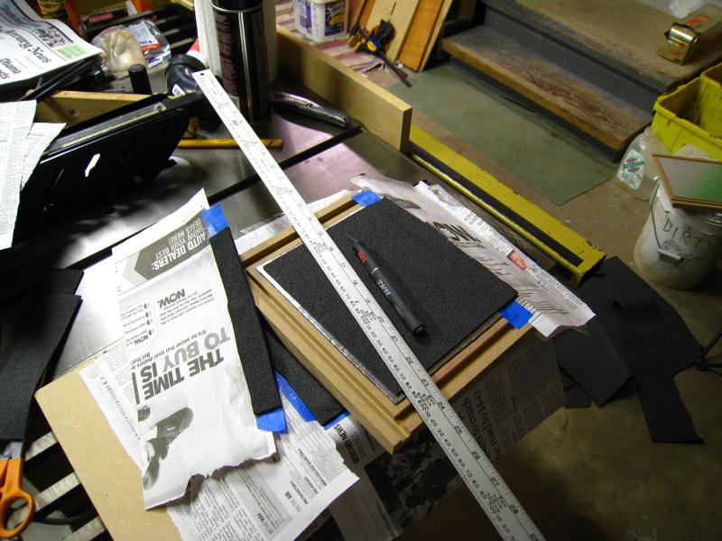
On top of the deadening, I put panels of closed cell foam (also had it from the car project).
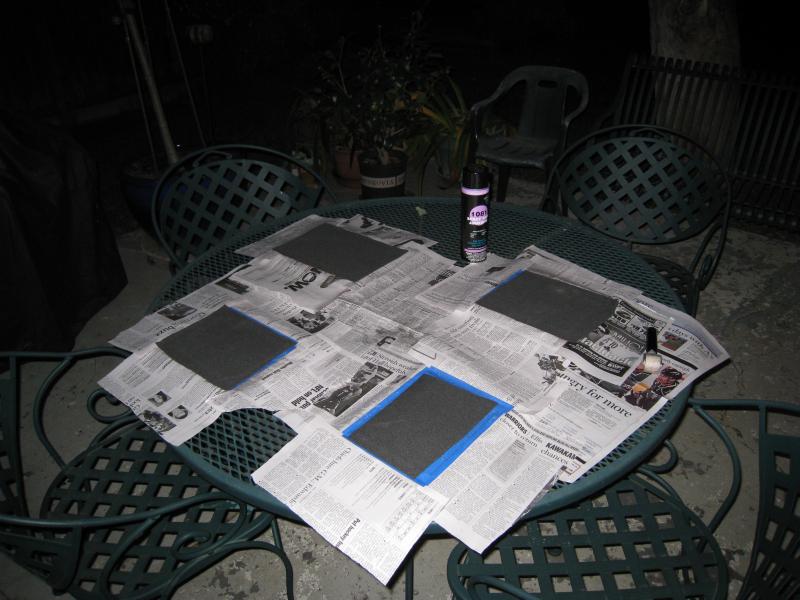
Trimming the foam off...I made it a bit oversized for easier fitting. Trimming an oversize piece is a lot easier than cutting the right size & trying to align it in one shot on contact adhesive!
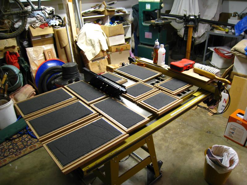
Here are the deadened panels. I opted not to use stuffing based upon reading I did on making ported boxes. It did not seem like it would provide much benefit, although my reading did suggest that the deadening panels would help.
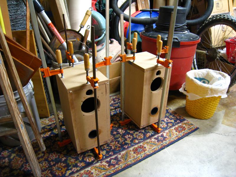
The first gluing round commences.
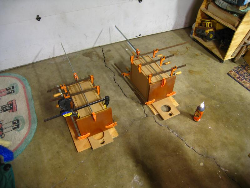
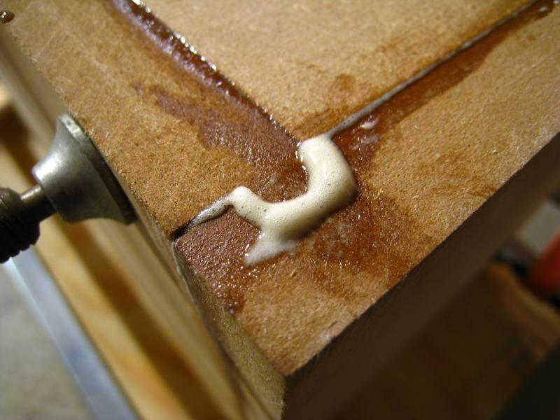
Gorilla Glue...this stuff is down-right silly! Impossible to wash off of skin, stains skin, stronger than the MDF itself & foamy when curing!
Silicone sealing the interior seams.
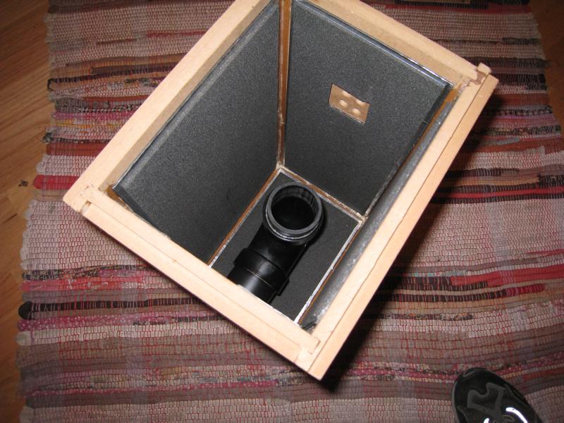
Test-fitting the port. Yes, it had to be curved in order to keep the proper length with the selected diameter (large diameter to keep the port air velocity low enough), AND stay at least 4" from all walls & the driver.
I had some butyl-rubber sound deadening with 6-mil aluminum foil bonded to it left over from a car project. I used it on all interior surfaces (front panels were done later).
I also left 0.25" around the edges for the silicone caulking I was going to seal the seams with.
On top of the deadening, I put panels of closed cell foam (also had it from the car project).
Trimming the foam off...I made it a bit oversized for easier fitting. Trimming an oversize piece is a lot easier than cutting the right size & trying to align it in one shot on contact adhesive!
Here are the deadened panels. I opted not to use stuffing based upon reading I did on making ported boxes. It did not seem like it would provide much benefit, although my reading did suggest that the deadening panels would help.
The first gluing round commences.
Gorilla Glue...this stuff is down-right silly! Impossible to wash off of skin, stains skin, stronger than the MDF itself & foamy when curing!
Silicone sealing the interior seams.
Test-fitting the port. Yes, it had to be curved in order to keep the proper length with the selected diameter (large diameter to keep the port air velocity low enough), AND stay at least 4" from all walls & the driver.
The final gluing round.
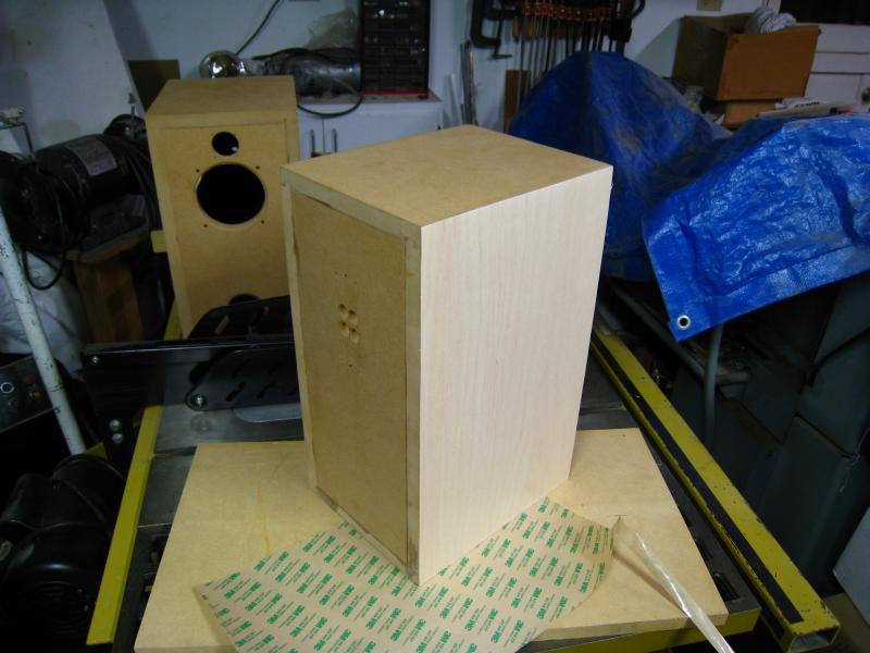
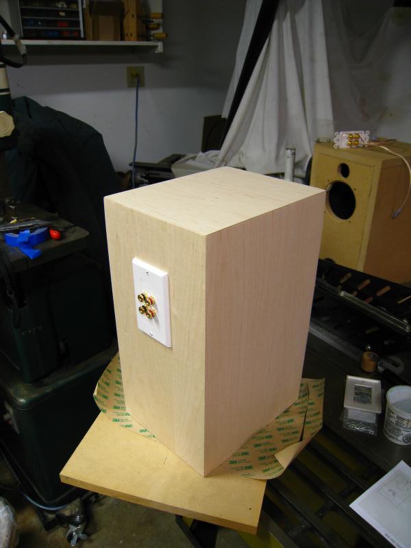
Drilling the rear panel for the connector plate. I also began veneering them...as much as I like bare MDF & all........
I used a wall-plate for the connections, with 5-way posts. It seemed simple, economical, and I rather liked the look. Of course, I later had to make proper provisions for sealing it (silicone around its base, and on the inside after the interior connections were made to seal the connector holes).
All veneered up..........
OK, ready to roll! After this, I put 6 coats of Deft clear lacquer finish on, let it cure for a month, wet-sanded it, and carefully applied one last coat. Once cured, I hit it with some 000 steel wool to give it a nice satin finish. I am very pleased with my first woodworking project...previous projects have involved 2"x4"'s, tolerances of 1" & hoisting car motors, so this was a little different.

Now that I have started in on the subwoofer to go with these (so much for all the work put into the ported design!), I will have a lot of extra polyfill. I'll probably stuff these boxes to reduce any reflections that might be occurring inside. The sub will get its own thread, eventually.
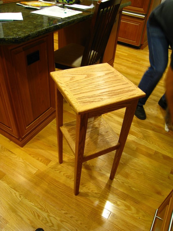
A second project, spurred from this, was some custom tables. I needed these off of my desk! The tables took a good ~5 weeks, but were well worth the effort. $150 worth of Red Oak stock lead to some sweet tables. I doubt I could get ones of this quality at a store anywhere, for less than twice that price.
Due to pic limitations on here, here's the directory with the images...I'll make an actual site for them eventually.
http://www.e30tuner.com/speakerbuilding/images/speaker1_tables/
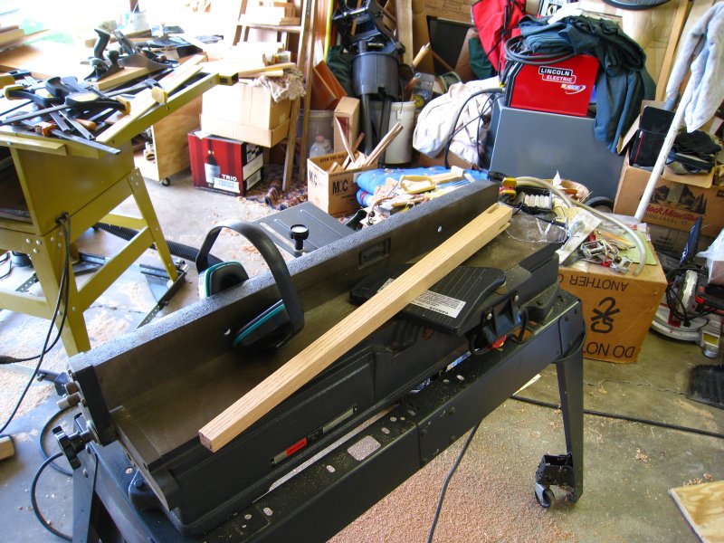
Tapering the legs on the planer.
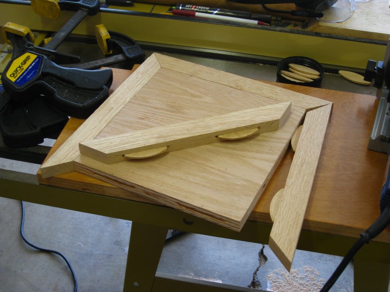
The form to keep it all square during assembly.

Putting together the surfaces for the mid-shelves.
Assembled, and ready for some Danish Oil...
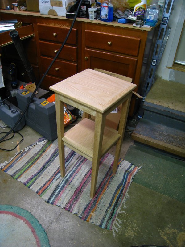
And, all done...
Drilling the rear panel for the connector plate. I also began veneering them...as much as I like bare MDF & all........
I used a wall-plate for the connections, with 5-way posts. It seemed simple, economical, and I rather liked the look. Of course, I later had to make proper provisions for sealing it (silicone around its base, and on the inside after the interior connections were made to seal the connector holes).
All veneered up..........
OK, ready to roll! After this, I put 6 coats of Deft clear lacquer finish on, let it cure for a month, wet-sanded it, and carefully applied one last coat. Once cured, I hit it with some 000 steel wool to give it a nice satin finish. I am very pleased with my first woodworking project...previous projects have involved 2"x4"'s, tolerances of 1" & hoisting car motors, so this was a little different.
Now that I have started in on the subwoofer to go with these (so much for all the work put into the ported design!), I will have a lot of extra polyfill. I'll probably stuff these boxes to reduce any reflections that might be occurring inside. The sub will get its own thread, eventually.
A second project, spurred from this, was some custom tables. I needed these off of my desk! The tables took a good ~5 weeks, but were well worth the effort. $150 worth of Red Oak stock lead to some sweet tables. I doubt I could get ones of this quality at a store anywhere, for less than twice that price.
Due to pic limitations on here, here's the directory with the images...I'll make an actual site for them eventually.
http://www.e30tuner.com/speakerbuilding/images/speaker1_tables/
Tapering the legs on the planer.
The form to keep it all square during assembly.
Putting together the surfaces for the mid-shelves.
Assembled, and ready for some Danish Oil...
And, all done...
Last edited:
WOW! that was your first project? fantastic. I hang my head in shame such are my meagre efforts...
Great stuff, so how do they sound??
Steve
Great stuff, so how do they sound??
Steve
nice work, bmwman, wish I could make boxes as nice.
The only thing I would have done different is to put a little stuffing behind the woofer to eliminate reflections.
re: the sub, consider dual subs, from ~150Hz down. Then you'd have a great 3-way system, 'specially if you bi-amp.
The only thing I would have done different is to put a little stuffing behind the woofer to eliminate reflections.
re: the sub, consider dual subs, from ~150Hz down. Then you'd have a great 3-way system, 'specially if you bi-amp.
WOW! that was your first project? fantastic. I hang my head in shame such are my meagre efforts...
Great stuff, so how do they sound??
Steve
Haha, now now, no need for shame! I have great respect for all DIY'ers (at least in audio, don't let me catch you putting home-made wheel spacers on your car!), and hopefully all respect is mutual! This is far form my first technical project, so I have had some prectice with patience & the whole design process.
How do they sound? I have been asked that (this was all originally posted in the off-topic section of a very large car enthusiast forum) a few times. Of course, I think they sound awesome! I mean, after all the work that went into them, I think I would have to do something terribly wrong to DISlike them...sort of like how every parent thinks their kid is the best. I don't have children yet, so various projects serve in their place.
A good friend has built some speakers, and was doing it a few years before me. His sound great (he prefers back-loaded horns with Fostex full-range drivers). Compared to those, I would call these close. Compared to the various poop found at Best Buy & other brands consumers are familiar with, these beat the heck out of them, and at a fraction of the price.
So, I am very happy with them. After prolonged listening, the treble does become a little fatiguing to my ears, partially because of the cheesy XO job I did (look at the computed response plot at the start), and probably because of the cheap tweeters having moderate distortion (you get what you pay for in many cases). Still though, I can listen to these all day, compared to the Cambridge SoundWorks PC speakers I had prior to this.
Really impressive, especially seeing as it's your first project of this type 😱
Those routered grooves are very precise! I did a similar thing with a subwoofer box once, it wasn't too bad but by the time came to fit the opposing side I needed a lot of clamping pressure to pull it into line 😱😀
Those routered grooves are very precise! I did a similar thing with a subwoofer box once, it wasn't too bad but by the time came to fit the opposing side I needed a lot of clamping pressure to pull it into line 😱😀
nice work, bmwman, wish I could make boxes as nice.
The only thing I would have done different is to put a little stuffing behind the woofer to eliminate reflections.
re: the sub, consider dual subs, from ~150Hz down. Then you'd have a great 3-way system, 'specially if you bi-amp.
Stuffing is in the mail...I ordered some extra for these when I got the parts for my subwoofer project.
I thought about dual subs, but opted to go with one, in a rather large ported enclosure (121L final internal volume, accounting for bracing, the monster 4" port, super thick acoustic foam on the walls & the driver itself). It uses the TangBand WQ-1858. I will stuff it to around ~1.1lbs/ft^3 density with polyfill, which will give 10-35% more effective internal volume (~160L is ideal) depending on which articles/opinions you read about the stuffing. Given these properties, I can meet my goal of a -0.5dB point at 20Hz.
Really impressive, especially seeing as it's your first project of this type 😱
Those routered grooves are very precise! I did a similar thing with a subwoofer box once, it wasn't too bad but by the time came to fit the opposing side I needed a lot of clamping pressure to pull it into line 😱😀
Thanks! Yes, clamping is super critical. Not ALL of the edges lined up quite as perfectly, but I wasn't going to put up pics of a BAD joint haha. Having 12 wood clamps available sure helps.
Lol you did alot better then me on my first project, thats for sure! Great job
Haha, thanks. I can only call this my first audio project though. I have been in the car scene for a number of years now, and have a number of hours on a vertical mill, lathe & MIG welder. Metal costs a lot more than wood (well, SOME wood), so I was already in the habit of being patient & measuring 5 times before making a cut. Not too many years ago I was impatient & impulsive with fabrication, and yeah these wouldn't have turned out so well, to say the least.
That's damn impressive woodworking for a first project.
I'd try regular Titebond wood glue for your next project. It's plenty strong (especially if you are going to build tongue in groove joints like that) and much easier to work with.
I'd try regular Titebond wood glue for your next project. It's plenty strong (especially if you are going to build tongue in groove joints like that) and much easier to work with.
The ACTUAL documented impedance of the tweeter was used for the XO calculations here....digitized from the data sheet. I wrote a custom VB app to interpolate between the digitized points (SPL & impedance values for both speakers at the same frequencies) so that I would have nice conformity between the 2 speakers should I choose to go passive with both.
Can you explain this further? How did you generate the frequency response graph you posted? How did you calculate the crossover topology and component values, exactly?
Thanks!
Can you explain this further? How did you generate the frequency response graph you posted? How did you calculate the crossover topology and component values, exactly?
Thanks!
As you probably know, any reputable driver will have a datasheet available. These sheets should include the 1W/2.83V frequency response & impedance curves for the driver. Much of the time, they are of crappy visual quality, but usable.
There is free digitizing software out there. I happen to like Engauge Digitizer which is free, and allows you to specify semi-log & log-log scales. Paste in a screenshot of the response curves. You pick 3 points on the main axes (typically max Y, lowest X/Y, & max X), choose linear or log scales, & go to it. Visually picking points along the curve image, you can capture all of the "important" parts of it. With the axes specified, the picked points will usually work out perfectly. You can export it to a CSV file.
That's all good & nice, but if you actually want to manipulate the frequency response with simulated passive XO parameters, you need impedance & response values (Y's) at the SAME frequency values (X's). That's why I wrote a custom app to do that. Capture all the important points on the screenshot, & export them to a CSV file. Do this for the frequency response & impedance curves if you want to do passive calculations. My app lets me specify the frequency intervals & step sizes (for example: 1Hz increments from 10Hz to 1000Hz, 10Hz increments from 1000Hz to 10kHz, 100Hz increments from 10kHz to 25kHz). This is accomplished with simple linear interpolation between the digitized points made by Engauge. Then you just paste the data into MS Excel, or equivalent, & you can start loading these suckers up with formulas.
So in case there was any confusion, the response curves in the first post are NOT from measurements, but rather based upon the datasheets for the drivers. Certainly, real-life response will be different.
Also, in a similar fashion, I digitized WinISD curves, correlated them to the actual driver response & interpolated on them to account for the effects of the enclosure in the computed response curve.
If there's interest, I can share the application I wrote. I might put a bit more work into it first, though, to make it more user-friendly. Apps you write for your own personal use are usually un-friendly to others since you don't have to put in any real "idiot-proofing" since you know all the quirks!
are you going to leave woofers unfiltered?
very nice work with cabinets.
For now, sure. The plan is to tri-amp it all once the sub is done. From the start I had planned on ending up with a fully active rig, so I didn't put too much time into the passive XO setup...just enough to attenuate the tweeters -6dB to better match the woofers, and keep them safe from low frequencies.
My trusty helper...watching...waiting...(for food)
I had some butyl-rubber sound deadening with 6-mil aluminum foil bonded to it left over from a car project. I used it on all interior surfaces (front panels were done later).
I also left 0.25" around the edges for the silicone caulking I was going to seal the seams with.
On top of the deadening, I put panels of closed cell foam (also had it from the car project).
Trimming the foam off...I made it a bit oversized for easier fitting. Trimming an oversize piece is a lot easier than cutting the right size & trying to align it in one shot on contact adhesive!
Here are the deadened panels. I opted not to use stuffing based upon reading I did on making ported boxes. It did not seem like it would provide much benefit, although my reading did suggest that the deadening panels would help.
The first gluing round commences.
Gorilla Glue...this stuff is down-right silly! Impossible to wash off of skin, stains skin, stronger than the MDF itself & foamy when curing!
Silicone sealing the interior seams.
Test-fitting the port. Yes, it had to be curved in order to keep the proper length with the selected diameter (large diameter to keep the port air velocity low enough), AND stay at least 4" from all walls & the driver.
Wow, great job you did there !
About the aluminium : is that shielding ?
I thought EM shielding had to be done with either steel or nickel.
- Status
- Not open for further replies.
- Home
- Loudspeakers
- Multi-Way
- My First DIY Loudspeakers [Story & Pics]