
Is there a problem with using ferous (magnetic) fixings through the middle of an inductor?
Oooooh yes, that's a BIG! no-no.
Magura
")
Some stainless is more magnetic than others. It would be easy to test with a magnet.
If there are any superior properties in using a foil inductor over a ordinary wire inductor, the superiority would be completely ruined by using a magnetic core in the center.
I see another problem in your photograph. The inductor with the red tape has its axis parallel to the bigger foil inductor. There will be coupling of magnetic fields--one coil inducing a signal in the other. Inductors should be lined up with their axis at right angles to each other to minimize the coupling.
Also, the nearer one coil is to the other, the more coupling there is. I would place the coils as far away from each other as I could on the board.
I am a physics teacher and I have demonstrated this effect many times to my students.
Its perfectly fine to use a ferrous bolt as long as there is no galvanic connection between the top and bottom of the inductor or toroid. In your case the top cover seems to be plastic so it should be fine.
You're confusing the effect of creating a shorted turn, with that of having a different/wrong magnetic path.
The bolt will certainly destroy the advantage of using an air-core coil.
Firstly, you've added core losses.
Secondly, the value of the inductor, and therefore the crossover frequency, will change!
Last edited:
Yes there will be a big problem Pick up your multimeter, measure the inductance of the air coil, then put the screw in and measure again, it should raise quite a lot. I have already seen the measured difference at the xovers of a commercial loudspeaker where they used ferous screws to mount the coils.
Pick up your multimeter, measure the inductance of the air coil, then put the screw in and measure again, it should raise quite a lot. I have already seen the measured difference at the xovers of a commercial loudspeaker where they used ferous screws to mount the coils.Yes there will be a big problem
Not to mention, it's more than a static shift- the screw will saturate, so your inductor will lower in value with higher-power impulses- just when you need a lowpass to do it's job the most, to prevent breakup in metal cones, for example. So you can't design around it.
Hi Guys
I have just tested it with a LC meter, and my stainless steel bolt does not make any difference.
I don't know why I did not try this before - my bad.
I pulled out the bolt and tested its magnetic characteristics against a speaker driver magnet. In this case, the stainless steel bolt would not support its own weight, and indeed gave little indication of any ability to be magnetised. Some other stainless bolts in my box were mildly magetisable however.
In the interests of experiment, and of this thread, I inserted a hex key (which was easily magnetised to the driver magnet) into the inductor core, and it increased the inductance from 1.4mH to 1.85mH. Beware.
Cornelis: I am aware of the problems of placing inductors close to each other. There is a good article here: http://www.troelsgravesen.dk/coils.htm
The PCB and the XO have been designed by an experienced engineer, by calculation and by ear. He has sold many kits, so I asume that all is good: AOS Studio 12: http://www.aos-lautsprecher.de/indexE.html
I will however mention this to him when I am next in contact. It had already concearned me.
The web page showing the placement of the coils shows very little change in the value of the inductance. I would expect that and it is irrelevant to the point I was making.
The point I make is that two coils close together acts as a transformer, where one coil, the primary, induces a current in the other, the secondary. In the usual transformer an iron core is used to get the coupling is close to 100%, and in your situation is is closer to 1%. The effect will be small, and may even be difficult to detect by listening, but is so easy to eliminate the magnetic coupling altogether by simple placement of the coils with axis at right angles to each other.
Some manufacturers use hot melt glue to mount coils which seems fine to me, as it nonmagnetic and gives great flexibility in positioning the coils. Using a bolt to secure a coil for the sake of mechanical security seems over the top for me unless you intend to throw your crossover around the room.
Unless you're also using some zip ties, I would not depend on hot glue alone for a coil that heavy.Some manufacturers use hot melt glue to mount coils which seems fine to me, as it nonmagnetic and gives great flexibility in positioning the coils. Using a bolt to secure a coil for the sake of mechanical security seems over the top for me unless you intend to throw your crossover around the room.
An air coil used for a CLC power supply would need to be secured properly. I am trying with a M4 (4mm) zink screw, but then I ran into another problem. The spacer is 2 mm away from the copper foil of the air coil, which could make the whole chassis live. Another option is to use a M6 screw with a wider head that would not need a spacer and would increase the distance to the foil. I have isolated the copper foil with heat shrink tubing, but I don't want to bet my life on heat shrink tubing. But an M6 means more metal in the hole where there should not be any metal, so I am at a loss.
Zip tie is an option, but the plastic can age and snap, especially as I am going to "hang" my coils vertically on an L-bar.
An unrelated but maybe not so unrelated example: Last night I used 50 zip ties to make my bicycle wheels ride on ice. It worked pretty good, but I lost half of the zip ties in 10 minutes. Even if that was an extreme test, it proves zip ties are rather fragile and can easily snap.
Edit: Stainless seem to be much less magnetic than a zip tie when I tested with a fridge magnet. So I may end up using a M5 stainless screw. I will also put a big blob of silicone on the screw head to to make sure that the piece of foil will not touch the screw and electrify my chassis. Between the L-bar and the air coil I will use two sheets of silicone, the kind used to isolate and transfer heat between mosfets and heatsinks.
Edit#2: The M5 stainless screws with angled head was perfect for Mundorf air coils. But the silicone pads keep moving. I will have to use wood, even if it is flammable...
Last edited:
Do you think much current will be induced in this configuration/orientation? This is wound in a different direction than toroidal transformer, for example, and there is no shorted turn.electrically conductive
I don't know. I am just a hobbyist, and this is my first attempt at a CLC PSU for Firstwatt amp. Maybe a brass plate would work to, but the zink L-bar is fine, although it is quite magnetic. I am worried about how the coils will interact with each other. I don't want to create a transformer, like someone suggested earlier in this thread.
2 times 70.000uf - 2.7mH - 70.000uf. last 70.0000uF is then bypasses by a 10uf film cap, and maybe also a 0.1uF.
The screw must be there, and this is the least magnetic screw I could find and it is safe from the foil sticking out. The foil has now two layers of shrink tubing at the area of the screw.
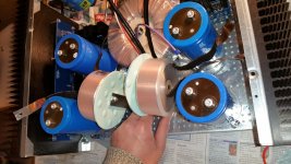
This is a tight space, but I am trying to be creative when I mount them. Any suggestions on how not make them induce each other, the power tranformer (should be shielded) or the audio transformers on the amp boards? The audio tranformers are located on each side where my hand is.
- Status
- This old topic is closed. If you want to reopen this topic, contact a moderator using the "Report Post" button.
- Home
- Loudspeakers
- Multi-Way
- Mounting Inductors with ferous bolt?