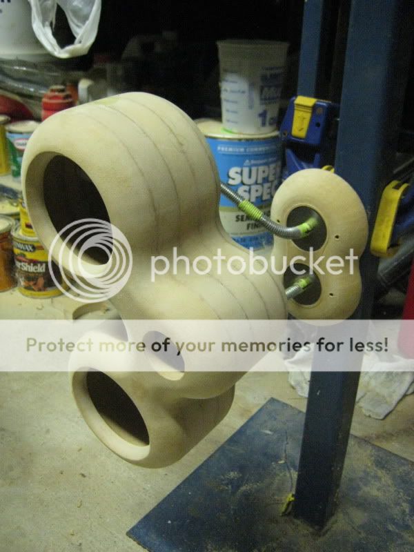
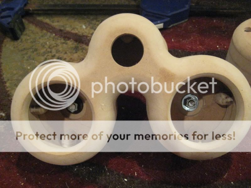
Damn! You read too much Dr Seuss when you were a kid! These HAVE to be called the Lorax Enclosure, surely.
Niiiiiiiice.
Guilty. Although I kind of feel more inclined to give them some sortofcellular name. Like Mitosis or something.
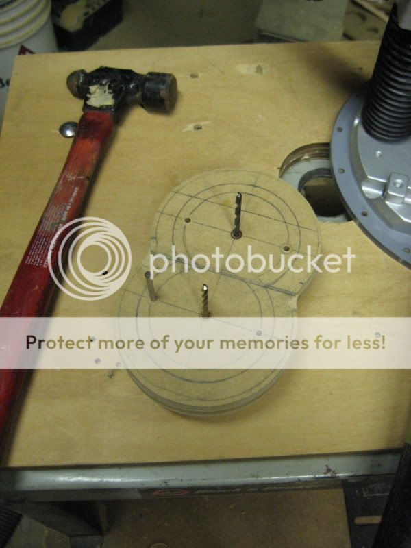
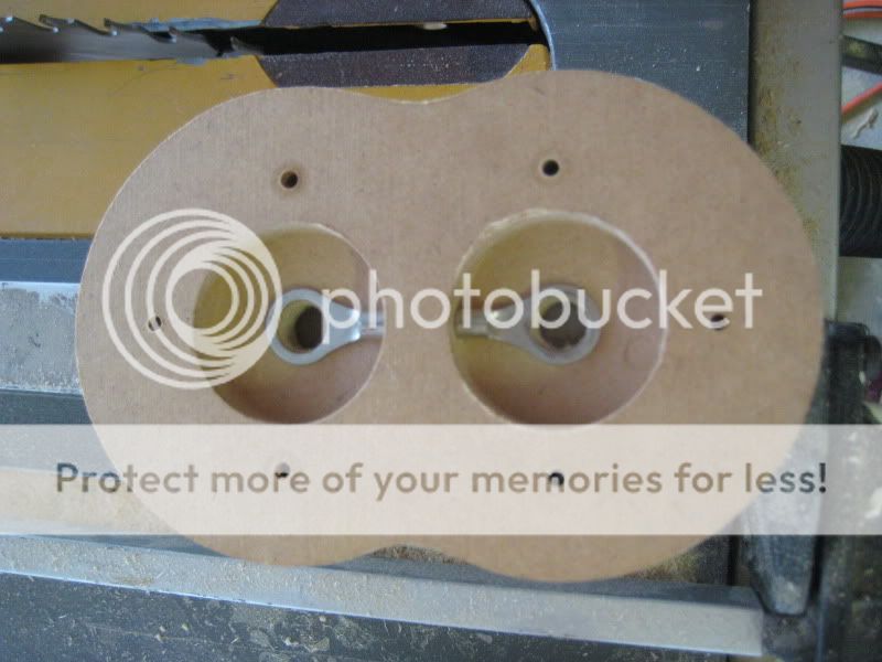
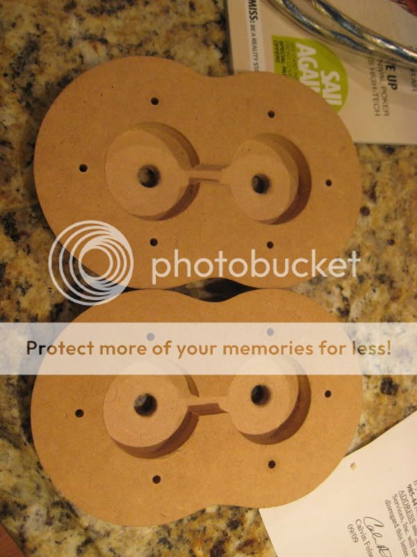
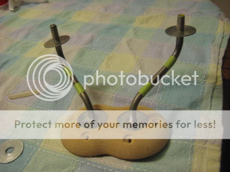
Well, I threaded the fender washers, and they all turn smoothly now

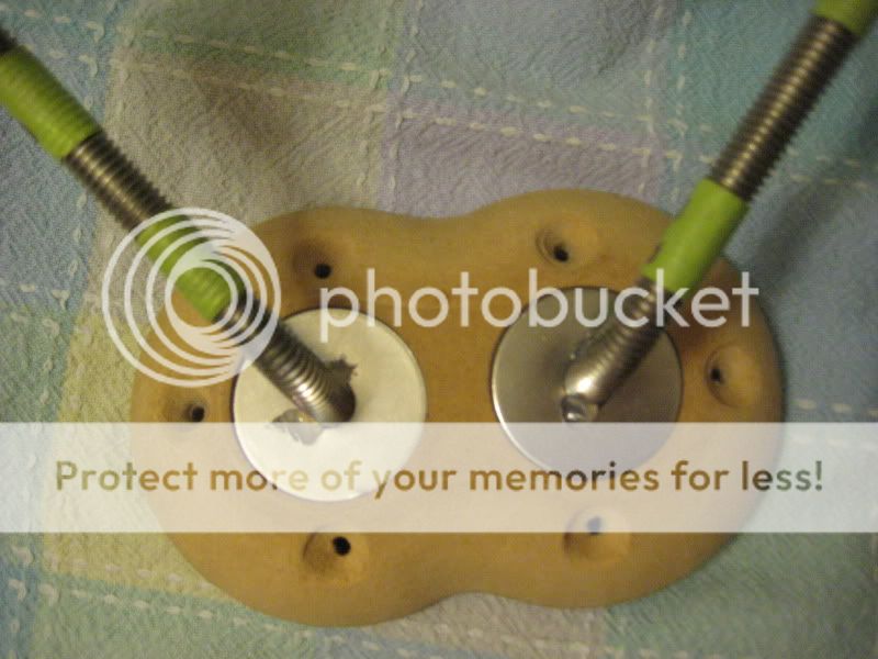
I also drew out and drilled the mounting holes for the wall plate on the stencil piece.

Then I used the pin from the Jasper Jig and some 1/8" drill bits to keep the two pieces in place as it drilled them.


Bow-chicka-wow-wooow

Fun build, have enjoyed following along immensely!
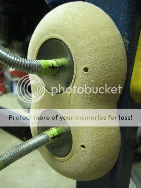
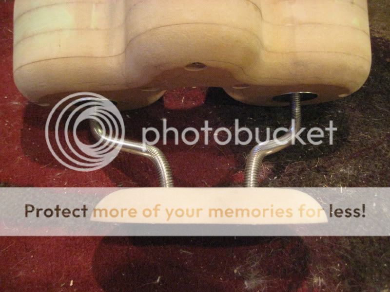
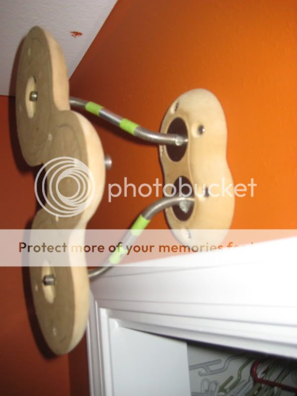
May I humbly suggest ( unless you like the look of the threads ) that you cover the threaded rod with a piece of suitably sized, and colored ( to your finish spec. ) flexible tubing...
For instance, fuel line; black, or heater hose; usually can be found in red or black...
Just a suggestion.
Have you determined how you will finish the MDF?
John
Fun build, have enjoyed following along immensely!
May I humbly suggest ( unless you like the look of the threads ) that you cover the threaded rod with a piece of suitably sized, and colored ( to your finish spec. ) flexible tubing...
For instance, fuel line; black, or heater hose; usually can be found in red or black...
Just a suggestion.
Have you determined how you will finish the MDF?
John
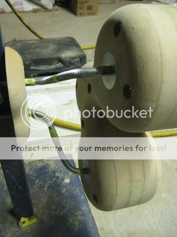
I actually really like the exposed threads, which is why I hunted down a stainless rod. Someone on another forum has suggested heatshrink, which I may use on another project, but not this one.
For finish I'm going to clean them up by sealing and then bondoing them, then I will probably hand them over to the painter at my girlfriend's dad's body shop. I was originally thinking an ultra pure white, but I may wind up going with somethind darker to contrast with the stainless steel. Maybe a slate grey, or there is an orange I like that is an oem color for Hyundai Tiburons (the newer body style).
With a lot of sanding, MDF can look pretty slick. These are some other ones that I had painted at the shop
Oh, and I just noticed this while browsing PE. Is Aura selling off designs or is this just standard imitation? The specs aren't exactly identical, but they're not off by much.
http://www.parts-express.com/pe/showdetl.cfm?Partnumber=290-210
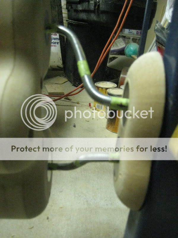
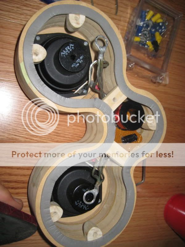
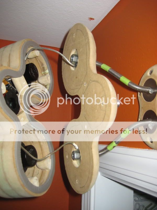
The stainless turned out to be much harder to bend. I wasn't sure if it would be easier or not, as it seems softer since it scratches so easily.
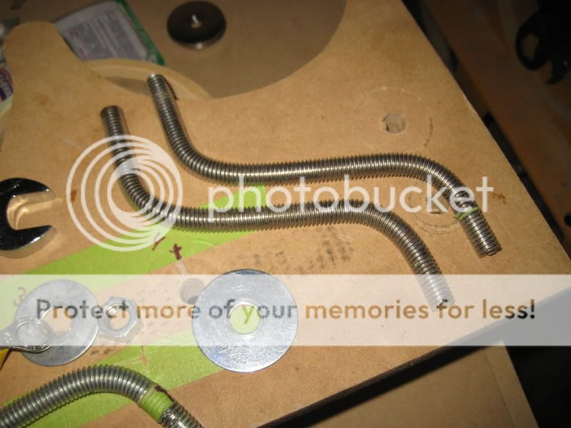
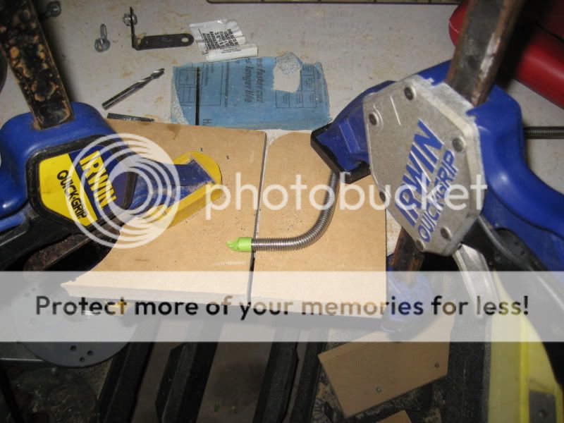
After some really messy ends from cutting with the Dremel, I decided to use the jigsaw to cut the threaded rod when I found an extra metal blade.
They look great with the stainless washers. I'm still thinking about hitting all of the hardware with the torch. I had a hot spot when cutting with the jigsaw and the bluing looked really great.
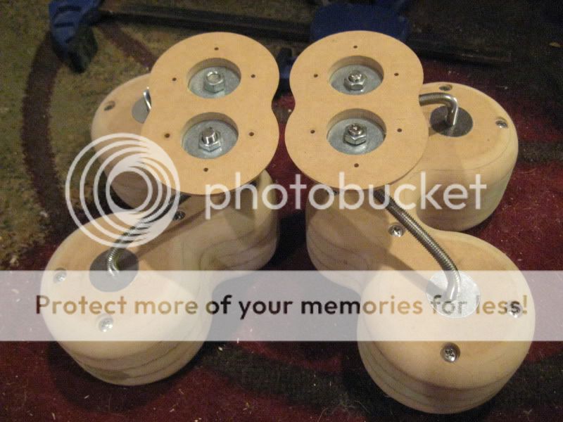

I still have lots to do. Lots of sanding, trim the rods, countersink the screw holes, more sanding, etc. Think I might at least have these guys up and working (unpainted) by the end of the weekend.
After some really messy ends from cutting with the Dremel, I decided to use the jigsaw to cut the threaded rod when I found an extra metal blade.
They look great with the stainless washers. I'm still thinking about hitting all of the hardware with the torch. I had a hot spot when cutting with the jigsaw and the bluing looked really great.
I still have lots to do. Lots of sanding, trim the rods, countersink the screw holes, more sanding, etc. Think I might at least have these guys up and working (unpainted) by the end of the weekend.
I haven't posted anything in about 3 days, so I have way too much to post at once, so I'll probably be doing it in sections. I think I have about 50. Anyone who wants to check out progress images before posting them, I usually have them in my Photobucket.
It was pretty hot all weekend, so I tried to do minimal work outside, so I decided to start working on the wiring.
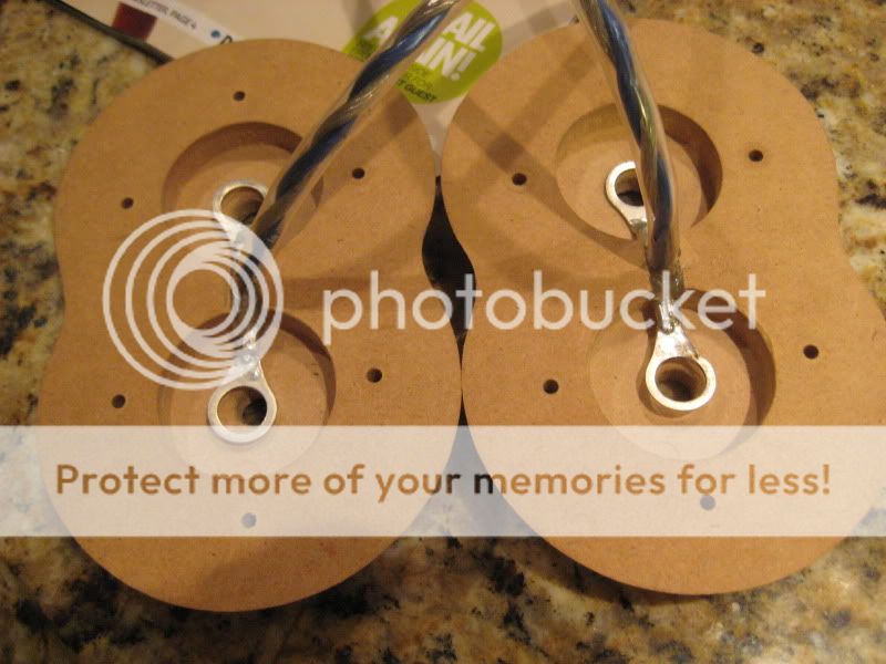
First I started by stripping off the plastic on the crimp connectors I've been using... they look messy and I prefer to heatshrink them myself.
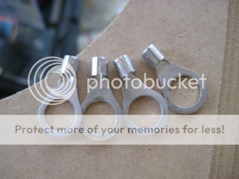
Without the plastic, they basically line up with the edge of the washer groove. I'm going to run them on the router and cut a 1/4" groove into them so I can have the wire split flush.
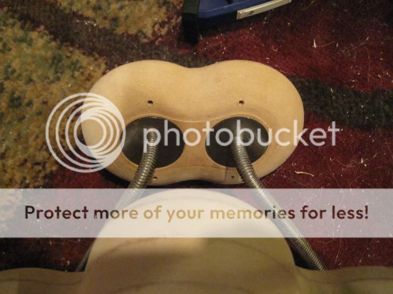
Then I started on the pigtails, using some sleeved speaker cable that I had left over from some other projects. I used spade connectors and stripped/heatshrunk all of them too. Once the two spades were isolated, I covered the whole end in clear heatshrink so it can be pulled through the wall more easily, if need be.
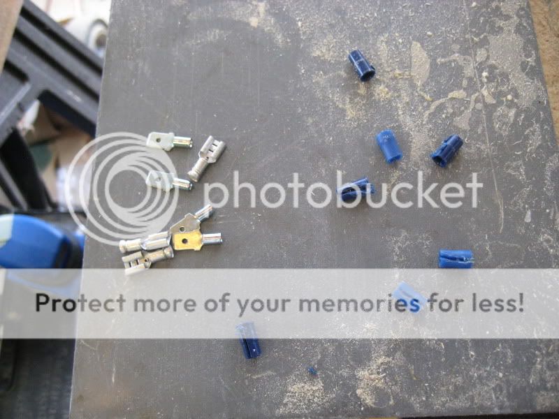
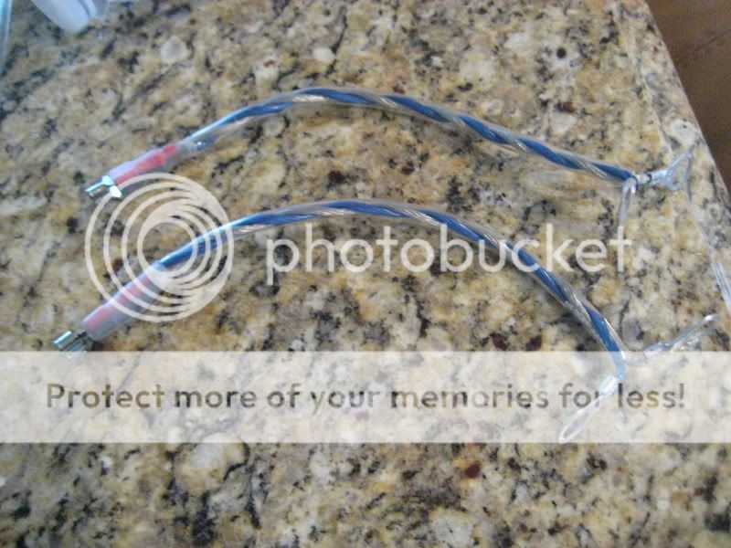

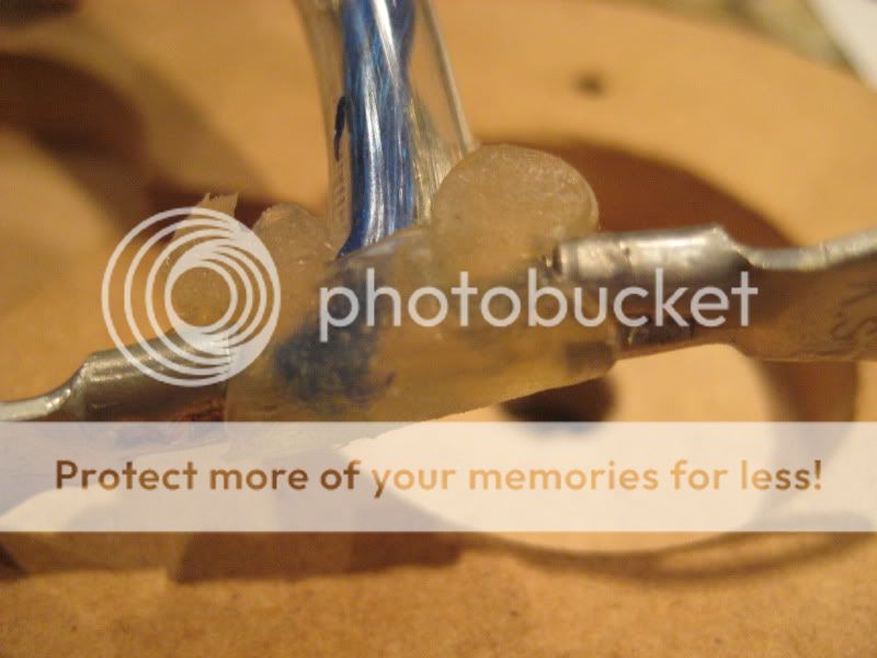
Once the pigtail was done, I taped up the groove, and set pigtail in place, filling up the groove with hot glue. I wasn't able to use heatshrink on that end, as there was no room to fit it, but I did want some sort of insulation.

It was pretty hot all weekend, so I tried to do minimal work outside, so I decided to start working on the wiring.
First I started by stripping off the plastic on the crimp connectors I've been using... they look messy and I prefer to heatshrink them myself.
Without the plastic, they basically line up with the edge of the washer groove. I'm going to run them on the router and cut a 1/4" groove into them so I can have the wire split flush.
Then I started on the pigtails, using some sleeved speaker cable that I had left over from some other projects. I used spade connectors and stripped/heatshrunk all of them too. Once the two spades were isolated, I covered the whole end in clear heatshrink so it can be pulled through the wall more easily, if need be.
Once the pigtail was done, I taped up the groove, and set pigtail in place, filling up the groove with hot glue. I wasn't able to use heatshrink on that end, as there was no room to fit it, but I did want some sort of insulation.
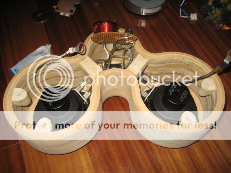
And now, more wiring:
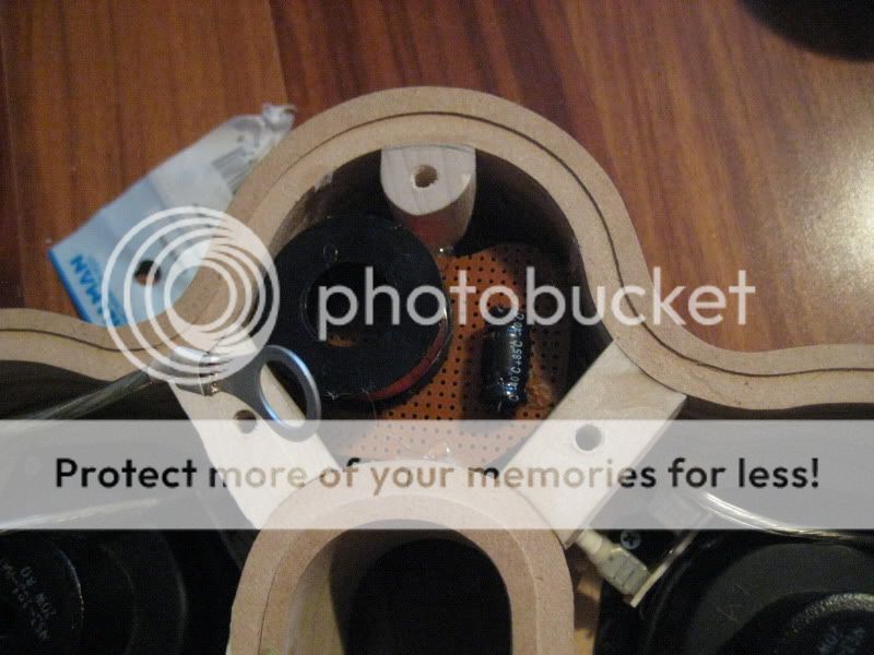
The prefab crossovers that I am going to use for now come on a pretty normally-sized crossover board, but its far too big for this project, so I removed the components and I will probably use the board itself for another 2nd order in the future.
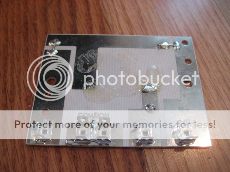
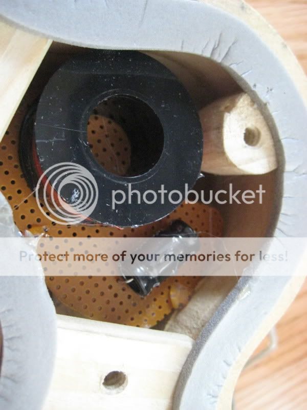
I mounted the components to some pcb board that I had laying around, that I trimmed to fit behind the tweeter.
For the crossover wiring I did everything in sections, so that the time spend soldering in the garage was at a minimum.


My lovely little work area for the moment:
Soldered and hotglued in place:
And now, the crossover installation progress:
Drivers in
Tweeter wired up

Slowly, but surely...
The prefab crossovers that I am going to use for now come on a pretty normally-sized crossover board, but its far too big for this project, so I removed the components and I will probably use the board itself for another 2nd order in the future.
I mounted the components to some pcb board that I had laying around, that I trimmed to fit behind the tweeter.
For the crossover wiring I did everything in sections, so that the time spend soldering in the garage was at a minimum.
My lovely little work area for the moment:
Soldered and hotglued in place:
And now, the crossover installation progress:
Drivers in
Tweeter wired up
Slowly, but surely...
This is a picture of the old wiring job I did. It wound up being too short and I had virtually no room when trying to bolt on the rods from inside. I only used it for testing while I wired up the new crossover.
The crossover boards themselves are glued in for the moment. When I break them down to finish/paint them, I will probably glue some feet for them to sit on.
I also decided to start working on the source for these speakers, as I am going to want to test under the conditions under which I will be listening. The amp is a budget Radioshack Accurian Home Plug unit, which puts out about 25w per channel.
I'm going to make an enclosure for it, as this thing is butt-ugly. It'll mimic the shape of the speakers to some degree, and I'll be layering it like the speakers.
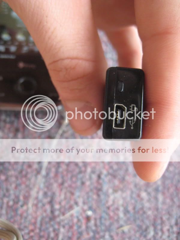
In addition to the amp using my tv's output, I'll be using the amp as a sort of dock for my phone. I use it for most of my listening, as my pc has no speakers and is in another room. The phone's only plug is a single minusb, and it comes with an adapter that allows the phone to charge while outputting audio to a 2.5mm, 3.5mm, or additional miniusb jack.

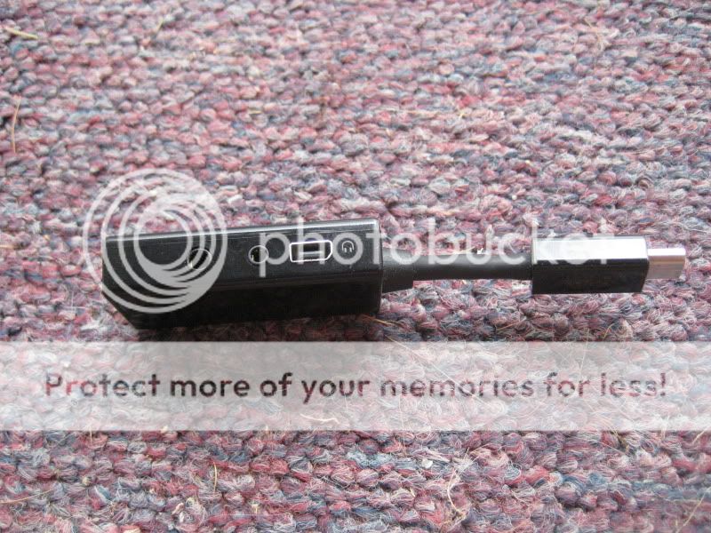
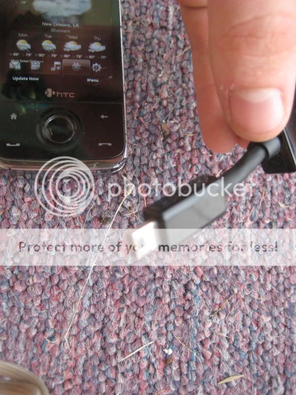
The phone also has tv-out, but you either need an ipod av/out cable, or in my case, a soldering iron. I'll have an rca out on the back to go to the tv for video. I'll either have a minusb in for charging on the back, unless I can find a steady 5v source on the board.
Unfortunately, I did have a pretty large setback. The plug base on my router combo decided to die on me, fortunately immediately after finishing drilling some holes. That leaves me with the countersink holes to do by hand. I tried to do one with the messed up router and it was way off. I did the rest by hand and they came out okay but I may wind up redoing the wall plates again, since I have the jig to make it still.
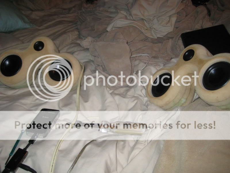
Shot of testing both out on teh bed
The crossover boards themselves are glued in for the moment. When I break them down to finish/paint them, I will probably glue some feet for them to sit on.
I also decided to start working on the source for these speakers, as I am going to want to test under the conditions under which I will be listening. The amp is a budget Radioshack Accurian Home Plug unit, which puts out about 25w per channel.
I'm going to make an enclosure for it, as this thing is butt-ugly. It'll mimic the shape of the speakers to some degree, and I'll be layering it like the speakers.
In addition to the amp using my tv's output, I'll be using the amp as a sort of dock for my phone. I use it for most of my listening, as my pc has no speakers and is in another room. The phone's only plug is a single minusb, and it comes with an adapter that allows the phone to charge while outputting audio to a 2.5mm, 3.5mm, or additional miniusb jack.
The phone also has tv-out, but you either need an ipod av/out cable, or in my case, a soldering iron. I'll have an rca out on the back to go to the tv for video. I'll either have a minusb in for charging on the back, unless I can find a steady 5v source on the board.
Unfortunately, I did have a pretty large setback. The plug base on my router combo decided to die on me, fortunately immediately after finishing drilling some holes. That leaves me with the countersink holes to do by hand. I tried to do one with the messed up router and it was way off. I did the rest by hand and they came out okay but I may wind up redoing the wall plates again, since I have the jig to make it still.
Shot of testing both out on teh bed
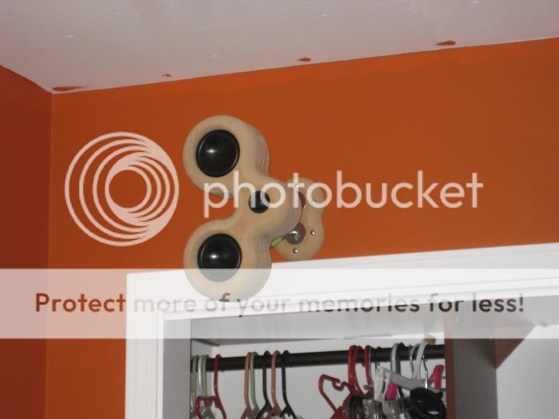
After finishing one wall plate, I decided to mount one on the wall to check it out. Here is how I have to mount them, step by step:
1. Mount rods to wall plate.
2. Mount to wall.
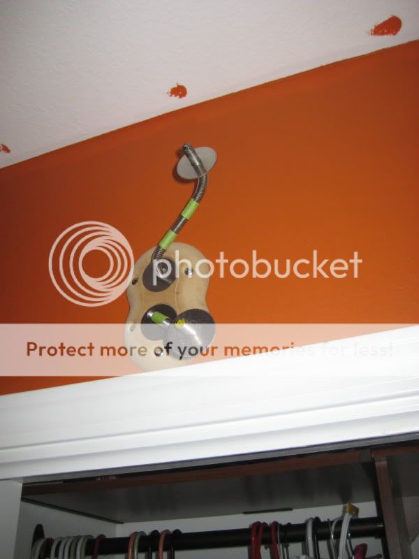
3. Mount to the wall correctly.
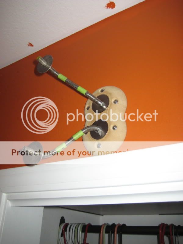
4. Mount back plate.
5. Screw front of speaker onto back.


6. ICE ARMS.
These are just some shots of the placement and whatnot. The TV is going in between the two closets, with the bracket at the same height as the speaker mounts, as it'll be going into that header above the left closet. I'm probably not going to have much room between the TV and the mirror, so I'm going to have to get creative with the shelf. The amp is going to go right below the TV. The TV itself is relatively small, like a 23" or something. Luckily it's a 4:3 screen, since I only have basic cable coming upstairs.

1. Mount rods to wall plate.
2. Mount to wall.
3. Mount to the wall correctly.
4. Mount back plate.
5. Screw front of speaker onto back.
6. ICE ARMS.
These are just some shots of the placement and whatnot. The TV is going in between the two closets, with the bracket at the same height as the speaker mounts, as it'll be going into that header above the left closet. I'm probably not going to have much room between the TV and the mirror, so I'm going to have to get creative with the shelf. The amp is going to go right below the TV. The TV itself is relatively small, like a 23" or something. Luckily it's a 4:3 screen, since I only have basic cable coming upstairs.
Alright, so updates... I have both up on the wall, unfinished, to check out the sound, and now to work on the sources I'll be using.

I listened to them for a couple of days with one of Radioshack amps that I have, with the stock preamp intact. I only used it for music for those days, from my phone, and it sounded decent. The tone controls have no center, nor are they marked, so it was hard to try and find a good point, and I seemed to be changing them with every song.
Then I plugged the rcas into my tv's output (I just put it up on the wall, still need to fish cable/power/speaker wires through the wall.) and it sounded pretty ******* bad. Everything sound hollow or something, kind of muffled, and just..off. I only tried one DVD (only source I have, since theres no cable on that side of the room right now) so I wasn't sure why it sounded so bad, and didn't really have the time to mess with it.
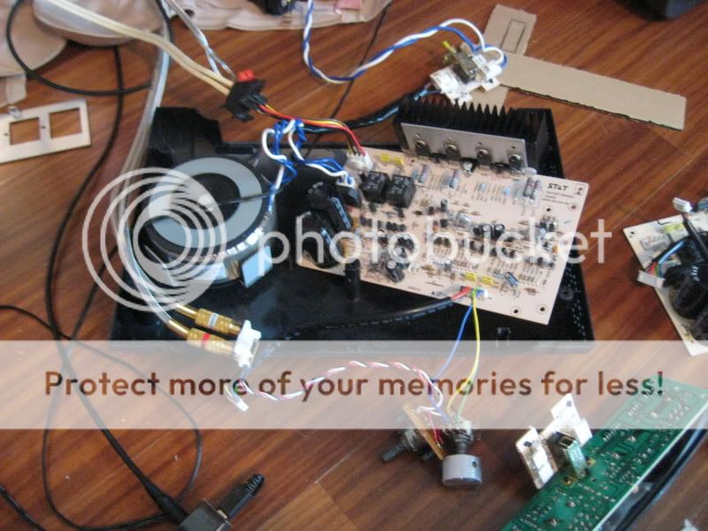
I had another amp that was sitting around, because I had replaced the preamp with a single pot, pulled from the preamp board itself, and the channels were all screwed up. The right only came in at full volume, and the whole thing was really quiet. I had put it aside for a while. I even had a new pot that i bought a few months ago at Radioshack and never put in. So I swapped out the pots for the hell of it, and sure enough it sound freaking wonderful now. No tone controls to deal with, no crappy preamp to mess stuff up.
I hooked them back up and was very pleased with the sound. I even tried the tv and it sounded flawless. Of course, I am using a different board/transformer/etc, so it may have just been a problem with the board. Now that that one is out of commission, I'll be taking out that one's preamp and whatnot.
I need to find some sort of rta software. I only have a ****ty onboard mic, but I figured it wouldn't hurt to get some sort of measurement in-room.
This is how it sits right now: Bad pot and new pot all hanging off, still need to mount the new one, the aluminum back wall of the amp is gone. Right now I have the heatsink screwed on, with a hot glue support. It's only temporary, while I tap some new holes, although I might just cut down the aluminum back plate.
I've been thinking about how to enclose the amp, and I remembered seeing this a while ago, and I figured I would mimick it.
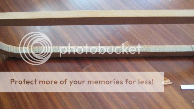
This is the frame jig I cut out. I think I might either do a natural finish wood in between painted mdf to match the speakers, or maybe continue with the stainless steel. Not sure atm.
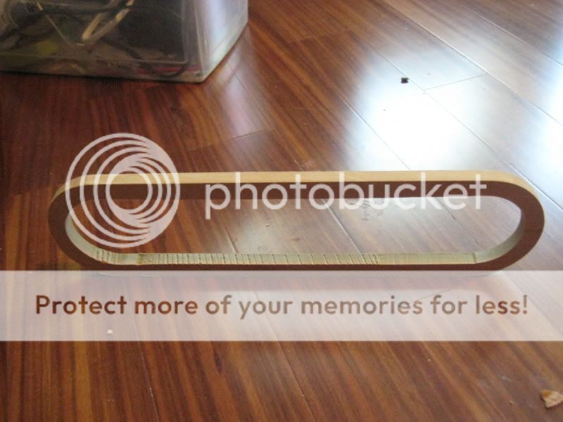
Also, you may notice the strange cut marks on the inside of the ring. That would be where the upcut bit grabbed the piece and dragged my finger into the bit. The weird thing was that the adjacent finger hurt much more than the one that was actually injured.
I'll spare you the gore, but I've dubbed it the Zombie Finger. It just took a little chunk out, but it looks more dramatic because it took some of the nail too. It's actually my first real injury via powertools. I've decided I'm definitely going to change the way I work with small/thin pieces.

I listened to them for a couple of days with one of Radioshack amps that I have, with the stock preamp intact. I only used it for music for those days, from my phone, and it sounded decent. The tone controls have no center, nor are they marked, so it was hard to try and find a good point, and I seemed to be changing them with every song.
Then I plugged the rcas into my tv's output (I just put it up on the wall, still need to fish cable/power/speaker wires through the wall.) and it sounded pretty ******* bad. Everything sound hollow or something, kind of muffled, and just..off. I only tried one DVD (only source I have, since theres no cable on that side of the room right now) so I wasn't sure why it sounded so bad, and didn't really have the time to mess with it.
I had another amp that was sitting around, because I had replaced the preamp with a single pot, pulled from the preamp board itself, and the channels were all screwed up. The right only came in at full volume, and the whole thing was really quiet. I had put it aside for a while. I even had a new pot that i bought a few months ago at Radioshack and never put in. So I swapped out the pots for the hell of it, and sure enough it sound freaking wonderful now. No tone controls to deal with, no crappy preamp to mess stuff up.
I hooked them back up and was very pleased with the sound. I even tried the tv and it sounded flawless. Of course, I am using a different board/transformer/etc, so it may have just been a problem with the board. Now that that one is out of commission, I'll be taking out that one's preamp and whatnot.
I need to find some sort of rta software. I only have a ****ty onboard mic, but I figured it wouldn't hurt to get some sort of measurement in-room.
This is how it sits right now: Bad pot and new pot all hanging off, still need to mount the new one, the aluminum back wall of the amp is gone. Right now I have the heatsink screwed on, with a hot glue support. It's only temporary, while I tap some new holes, although I might just cut down the aluminum back plate.
I've been thinking about how to enclose the amp, and I remembered seeing this a while ago, and I figured I would mimick it.
This is the frame jig I cut out. I think I might either do a natural finish wood in between painted mdf to match the speakers, or maybe continue with the stainless steel. Not sure atm.
Also, you may notice the strange cut marks on the inside of the ring. That would be where the upcut bit grabbed the piece and dragged my finger into the bit.
The weird thing was that the adjacent finger hurt much more than the one that was actually injured.
I'll spare you the gore, but I've dubbed it the Zombie Finger. It just took a little chunk out, but it looks more dramatic because it took some of the nail too. It's actually my first real injury via powertools. I've decided I'm definitely going to change the way I work with small/thin pieces.
- Status
- This old topic is closed. If you want to reopen this topic, contact a moderator using the "Report Post" button.
- Home
- Loudspeakers
- Multi-Way
- Funky NS3 MTM Build