Hey guys!
So, I've been doing this whole measurement thing, and finally getting the software to do what I want, and finally getting some confidence in my hardware setup. So, Monday I wanted to start putting things really to the test. I built myself a second microphone to test against the first, and I wanted to start getting scientific with measurements... different identical drivers in the same enclosure, the same driver in different enclosures, measuring inside and outside, different distances, etc.
I also wanted to test my setup against a speaker that I was fairly confident had a nice flat response. My roommate has a nice set of B&W 602s that he got 5 years ago or so, which I've always thought to be fairly fantastic sounding speakers, all things considered. SO, with his permission, I took one to the shop and took a look inside!
--------------
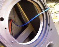
First, a look in the box. I was rather curious about this, because when you go to buy B&W speakers from a dealer, they show you all the fancy marketing footage about all the science that goes into the construction of their enclosures. They don't actually say what MODELS get what treatment, and the 602, being on the lower end of the line, is rather plain in this regard. Nothing special here... some rough composite board for the enclosure. It's not MDF, but a much looser composite. Don't know what to call it. One brace that extends from top to bottom, side to side. Sound damping comes from some basic 3/4" foam stuff
So, I've been doing this whole measurement thing, and finally getting the software to do what I want, and finally getting some confidence in my hardware setup. So, Monday I wanted to start putting things really to the test. I built myself a second microphone to test against the first, and I wanted to start getting scientific with measurements... different identical drivers in the same enclosure, the same driver in different enclosures, measuring inside and outside, different distances, etc.
I also wanted to test my setup against a speaker that I was fairly confident had a nice flat response. My roommate has a nice set of B&W 602s that he got 5 years ago or so, which I've always thought to be fairly fantastic sounding speakers, all things considered. SO, with his permission, I took one to the shop and took a look inside!
--------------
First, a look in the box. I was rather curious about this, because when you go to buy B&W speakers from a dealer, they show you all the fancy marketing footage about all the science that goes into the construction of their enclosures. They don't actually say what MODELS get what treatment, and the 602, being on the lower end of the line, is rather plain in this regard. Nothing special here... some rough composite board for the enclosure. It's not MDF, but a much looser composite. Don't know what to call it. One brace that extends from top to bottom, side to side. Sound damping comes from some basic 3/4" foam stuff
Attachments
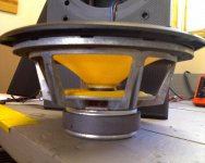
A quick look at the woofer itself. Kevlar cone, black pointy dustcap (not shown). cast frame. vented behind the spider. Not vented out the back of the pole piece, but the voice coil former has holes in it so air can move in there.. not sure if that's normal or not.
Attachments
Tweeter is next. It's a 1" aluminum dome thinger.
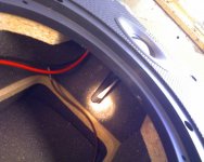
Looking inside you can see a little bit of nautilus inspiration trickling down into their lower line. The tweeter has a tiny TL rear compartment.
Upon closer inspection it looked as if the little plastic compartment was not straight. I reached in to feel it and sure enough, it was loose. The glue had mostly come off. Gotta wonder how long it's been like that!
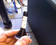
I pulled it the rest of the way off and looked closer. It's got a little taper to it, and is stuffed with a tiny bit of acousta-stuf-style damping. Very cute")
I re-attached it with some adhesive/sealant.
Looking inside you can see a little bit of nautilus inspiration trickling down into their lower line. The tweeter has a tiny TL rear compartment.
Upon closer inspection it looked as if the little plastic compartment was not straight. I reached in to feel it and sure enough, it was loose. The glue had mostly come off. Gotta wonder how long it's been like that!
I pulled it the rest of the way off and looked closer. It's got a little taper to it, and is stuffed with a tiny bit of acousta-stuf-style damping. Very cute
I re-attached it with some adhesive/sealant.
Attachments
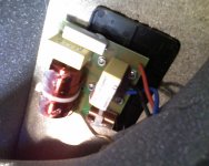
I took a peek behind the damping at the crossover. Very simple.
5 components. Looks to be a basic 2nd order with one resistor to match the level of the tweeter to the woofer. Since they're not my speakers I didn't go so far as pulling it out to check on the component values to see if I could work out what they were using for a crossover point
5 components. Looks to be a basic 2nd order with one resistor to match the level of the tweeter to the woofer. Since they're not my speakers I didn't go so far as pulling it out to check on the component values to see if I could work out what they were using for a crossover point
Attachments
And now the fun part!
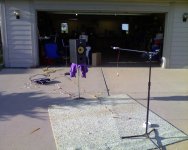
After the adhesive had cure on the tweeter's compartment, I put 'er up on the stand.
You can see here my EXTREMELY sophisticated measuring setup, complete with car-audio amplifier running off a radioshack 12volt switching power supply. I have the parts to build me a bench chipamp, but the car amp is nice for the time being as it has a very flexible active crossover, so I can do some basic initial listening and playing with crossover points.
The mic is a WM-61A capsule wired normally (without the Linkwitz mod). Sound card is an E-MU Tracker Pre. I'm using HOLMImpulse to take measurements. It's such a wonderful little application.
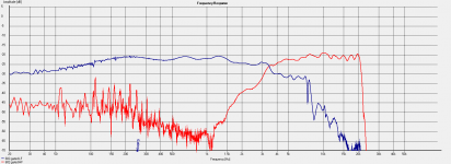
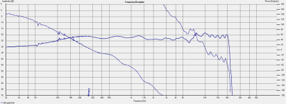
The first screenshot is seperate measurements taken of the woofer and tweeter seperately; the speaker has seperate binding posts on the rear for each, so you can bi-amp if you so choose, but you're still going through the crossover.
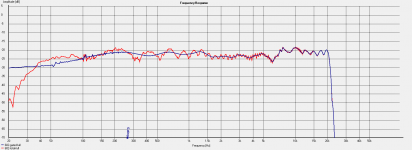
The second screenshot is both drivers together. I've overlaid the same measurement both gated and total response. Measuring outside is nice! I only really have the one reflection off the ground, so the total response is not out of hand.
The speaker does indeed measure quite flat! The tweeter runs a db or two hotter than the woofer, it seems, and that little dip at 6k appears to be a bit of crossover phase whackery, as both drivers measure nice and smooth in that region. It's pretty tiny though.
I guess I could have posted harmonic distortion graphs... but I don't really know enough about that to really trust the measurements. Maybe next time!
After the adhesive had cure on the tweeter's compartment, I put 'er up on the stand.
You can see here my EXTREMELY sophisticated measuring setup, complete with car-audio amplifier running off a radioshack 12volt switching power supply. I have the parts to build me a bench chipamp, but the car amp is nice for the time being as it has a very flexible active crossover, so I can do some basic initial listening and playing with crossover points.
The mic is a WM-61A capsule wired normally (without the Linkwitz mod). Sound card is an E-MU Tracker Pre. I'm using HOLMImpulse to take measurements. It's such a wonderful little application.
The first screenshot is seperate measurements taken of the woofer and tweeter seperately; the speaker has seperate binding posts on the rear for each, so you can bi-amp if you so choose, but you're still going through the crossover.
The second screenshot is both drivers together. I've overlaid the same measurement both gated and total response. Measuring outside is nice! I only really have the one reflection off the ground, so the total response is not out of hand.
The speaker does indeed measure quite flat! The tweeter runs a db or two hotter than the woofer, it seems, and that little dip at 6k appears to be a bit of crossover phase whackery, as both drivers measure nice and smooth in that region. It's pretty tiny though.
I guess I could have posted harmonic distortion graphs... but I don't really know enough about that to really trust the measurements. Maybe next time!
Attachments
Some other notes/conclusions:
The enclosure is extremely basic, which is pretty obvious right off the bat. As far as technology goes, the only thing happening with the box is the baffle itself. There's a particle board front of the box, and then that has a cast resin cover that laminates to that. This plastic part has the standard rounded-over edges. It also has this honeycomb pattern embedded into the front of it. Their marketing tells us that this helps dissipate standing waves from the tweeter. I gotta wonder how much hocus pocus that is. I didn't go so far as taking some putty and filling the entire baffle to see how it measured without the patter
Each of the drivers also has a bit of a rounded ring around it, too, that rises out of the baffle a little. Dunno what you'd call that or how much it would affect the sound.
The enclosure is obviously not too special, but it's not terrible. Generally a plain and well thought out speaker. Well built. The port is flared on both ends. It's obvious, though, that the value here is in the drivers.
These speakers cost my roommate 600 dollars USD for the pair, and he bought them in about 2001
----------
This was fun to do! I love taking things apart and seeing how they work, and learning from them, comparing them to my own work, etc.
I have a habit of driving all my friends cars whenever I get the chance... I can forsee myself doing a similar thing with any speakers I can get my hands on.
So, the question is, do you guys care about this stuff? If I were to keep getting my hands on other various speakers, would you be interested in me posting my results like this on a semi-regular basis?
So, the question is, do you guys care about this stuff? If I were to keep getting my hands on other various speakers, would you be interested in me posting my results like this on a semi-regular basis?
The short answer is YES
The long answer is YES PLEASE
The short answer is YES
The long answer is YES PLEASE
haha! awesome! well then. More to come, I suppose
I really need to learn more about measuring harmonic distortion. HOLMImpulse will calculate it, but I'm not sure how much those results will be affected by my microphone, room reflections, etc. I don't want to post anything unless I'm sure the results are fairly accurate. Anyone have any good information on this? If I was going to start measuring a whole bunch of stuff, I feel like I should at least try and get the whole picture. Frequency response doesn't say everything!
Also, i just now realized I forgot to show phase information. Lemme do that real quick...
Attachments
Good work, I'd surely like to see more of this stuff.
I seem to remember Zaph once saying that for HD measurements all you needed was a signal gen and a spectrum analyser, but I wouldn't know how it would work with swept as opposed to single tones.
So, since you constructed the mic yourself, could you tell us a bit about it?
Also, I don't know that the level you tested at is high enough - but I guess someone else will chip in. I think the reference standard is 1m at 2.83V/1KHz, but not 100% sure of that. For HD measurements one would look at slightly higher levels - 90dB or so?
Last edited:
Interesting stuff! I have DM602 S3 (your freind has S2 it appears). Differences on S3 I can see are different (more flush) woofer mounting, whole front baffle is gently curved and the "golf ball" texture on the reflex ports, intended to reduce air turbulence.
I am building a 3-way active system which will ultimately replace them, but I do still wonder if I'd have been just as pleased adding a good subwoofer to my DM602s, they are pretty decent really
I am building a 3-way active system which will ultimately replace them, but I do still wonder if I'd have been just as pleased adding a good subwoofer to my DM602s, they are pretty decent really
So, since you constructed the mic yourself, could you tell us a bit about it?
Also, I don't know that the level you tested at is high enough - but I guess someone else will chip in. I think the reference standard is 1m at 2.83V/1KHz, but not 100% sure of that. For HD measurements one would look at slightly higher levels - 90dB or so?
I've said about all there is to say, really, it's a Panasonic WM-61A capsule microphone attached to the end of a metal rod
My sound card is providing the voltage bias.As far as levels there's two reasons that I'm not cranking up the volume. One is that in the same measurement session I was getting data for the current set of speakers I'm building, which is an MTM using a MarkAudio Alpair5 as a mid-tweet. I wanted to get full-spectrum response graphs on the alpair5 without damaging it.
The second, and really the main reason, is that since I have NOT done the Linkwitz mod to my microphone, it will supposedly only handle something like 86db before starting to distort, and I wanted to steer well clear of that.
By the next set of tests I'm sure I'll have either modified the mic to handle more power (insert Tim Allen grunt here), or I'll have bought one of these:
http://www.parts-express.com/pe/pshowdetl.cfm?Partnumber=390-801
Good work, I'd surely like to see more of this stuff.
I seem to remember Zaph once saying that for HD measurements all you needed was a signal gen and a spectrum analyser, but I wouldn't know how it would work with swept as opposed to single tones.
So, since you constructed the mic yourself, could you tell us a bit about it?
Also, I don't know that the level you tested at is high enough - but I guess someone else will chip in. I think the reference standard is 1m at 2.83V/1KHz, but not 100% sure of that. For HD measurements one would look at slightly higher levels - 90dB or so?
The ARTA set of programs will measure distortion for you.
The ARTA set of programs will measure distortion for you.
well, so does HOLMImpulse, which I'm already using. What I don't know is how sensitive harmonic distortion measurements are to:
a) microphone quality
b) reflections, and
c) ambient noise
If I measure outside I get a decent amount of ambient noise (crickets, people mowing their lawns, etc). If I measure in the garage I get really really nasty reverberation. Does one truly need a proper anechoic chamber to get decent HD measurements? As far as the microphone... do microphones produce their own discernible harmonic distortion that would affect the measurements? These are my curiosities! Perhaps I will make another thread about this topic
and I did!
http://www.diyaudio.com/forums/showthread.php?p=1915009#post1915009
Please direct any HD discussion there!
http://www.diyaudio.com/forums/showthread.php?p=1915009#post1915009
Please direct any HD discussion there!
Hey There tresch!
I need to measure my project and I want to copy your setup. I want to do frequency response first and then get into distortion like in your other thread - - I have a Gen I Mighty Mike and some multimeters. You are using this application HOLMImpulse along with a particular PC sound card, is that right? Where can I get these?
Thanks,
Paul
- Status
- This old topic is closed. If you want to reopen this topic, contact a moderator using the "Report Post" button.
- Home
- Loudspeakers
- Multi-Way
- B&W 602 goes under the knife (pics and measurements)