Has anyone tried offsetting a terminus?
This is my thinking, the reason offsetting the driver works is that it is like a side branch, with one branch being the closed end and one branch being the open end.
So, if you offset the terminus you would still have the side branch only it would be at the terminus, so the impedance of the smal closed end pipe after the terminus would affect how much energy goes out of the terminus and how much goes into the closed end side branch..
Any ideas/comments ?
Hi,
This may or may not apply to your question.
I would answer your question "Yes".
In an MLTL simulation using Martin King's Mathcad worksheets, the position of the terminus DOES affect the response of the system.
Consider that the port response is a product of the resonance(s) from the cabinet.
Driver response is somewhat less affected by resonances from within the cabinet.
So, a position for the terminus may be found to balance the irregularities in response of the driver with those of the terminus (port) through cancelation.
Alternately, an ill-chosen terminus location may result in those peaks (or dips) in both the driver and port responses to be additive, ie. resulting in unpleasant irregularities in response.
This has been confirmed in the enclosures that I have built.
Optimization of response is one of the strengths I've found in using Martin's worksheets.
Can it be modelled without a port in the worksheets?
Yes, just enter a small length & x-section for the port: 0.01
The worksheets are available again.
 see Martin's website, and there is a Yahoo group set up to address questions.
schmeet said:I kinda meant, instead of moving a port can you move a terminus further up the line?
If you make the port have the same area as the terminus and have a length equal to the wall thickness the modeling should work just fine. I think the ML TL worksheet could be used to accurately explore this option if the inputs are thought out a litle bit.
I think i'm just gonna have to build one and see....
Whatever works best for you. With some simulations you could explore a number of different options in a few minutes and built the best candidate. Or you could sketch something and build it to see how it sounds and try and adjusting later.
For reference, PMC actually employ this configuration with one of their models; the GB1i to be exact: http://www.pmc-speakers.com/company/technology.php It's easy enough to model in Martin's worksheets using the proceedure he outlined.
When I model ML-TLs I find that seldom is the overall response optimally smooth with the port at the very end of the line. I usually have the driver's center located around 1/5 of the way along the line from the closed end and with that, the port's location is usually best a few inches from the end of the line, sometimes as much as 10 inches.
A tapered (or non-tapered) TL can be quickly and easily modeled with the ML-TL worksheet and you can place its terminus anywhere you choose.
A tapered (or non-tapered) TL can be quickly and easily modeled with the ML-TL worksheet and you can place its terminus anywhere you choose.
Nice one,
I'll have to get me the worksheets. I've tried offsetting the driver 1/3 and putting in a 1/5 sidebranch to try and get rid of the f3 and f5 harmonics and it kind of worked.
It actually made a new harmonic in between the two but it was somewhat reduced, and there was only a need for minimal stuffing.
I was hoping that instead of having the side branch on the pipe (which looks kinda odd!) i could offset the driver 1/3 and offset the terminus 1/5.
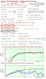
bjorno said:Hi,
FYI,I believe my simulation using an old version of 'MJK' worksheets shows all what happens if you offset the terminus of a TL.
b
1(1)
Thanks,
Looking at that, the black line (with the 1/3 driver offset and 1/5 terminus offset does seem to have less of a ripple, would be intersting to see it with no stuffing, as the ripples would be more pronounced, therefore the effect would be more noticeable.
Pete
- Status
- This old topic is closed. If you want to reopen this topic, contact a moderator using the "Report Post" button.
- Home
- Loudspeakers
- Multi-Way
- TL's Offsetting the terminus?