Hi I have been experimenting with active crossovers for my new line array open baffles, ribbon tweeters and subs. I notice that linkwitz seems to be using salen-key topology filters as is every other active filter used for crossover I have seen:
http://www.linkwitzlab.com/filters.htm#3
however the state variable filter seems to be supirior as it outputs LP and HP functions at the same center frequancy so mismatch between the LP and HP filters is eliminated.
I have attached a simulation of a 4th order State variable 4Khz crossover that has pi phase shift added to the lowpass output to allow both drivers to be in phase. It was designed using analogs filter tool:
http://www.analog.com/en/design-too...ign-sim-tool/Filter_Wizard/resources/fca.html
According to Wikipedia the group delay is several orders of magnitude below the threshold of audiability:
http://en.wikipedia.org/wiki/Group_delay
Attachments
Hi I have been experimenting with active crossovers for my new line array open baffles, ribbon tweeters and subs. I notice that linkwitz seems to be using salen-key topology filters as is every other active filter used for crossover I have seen:
Active Filters
however the state variable filter seems to be supirior as it outputs LP and HP functions at the same center frequancy so mismatch between the LP and HP filters is eliminated.
This thread hasn't gone on since it's posting. I was wondering if anything came out of this endeavor.
After trying out various topologies and comparing them, some in sims, I think I will be using the state variable topology instead of salen-key for my own filter design.
My goal is a 4 way filter, with some practical capability (jumpers or plug-in small cards) to make some adjustments to the frequencies.
Delays and level adjustments are easily added for each output.
So what I'm aiming at designing, is a 4th order, linkwitz-riley 4 ways filter, using the state variable topo.
Using one filter "cell" as a 2 way, I would first split the signal 2ways, and then add one more cell in each of those 2 ways, re-splitting to have 4 ways.
Other features that I plan to have is balanced inputs. No need for balanced outputs, as the filters would be right there physically near the power amps and the very short links to each amp don't warrant any balancing...
Will start some ltspice sims soon...
...the state variable topo.
...
Will start some ltspice sims soon...
I just happened to look at crossovers and had the same idea, so nice to see your post.
It seems that it should be possible to do a 2nd order SV with 2 op-amps rather than 3, at the cost of more common mode input.
Any ideas on this?
Best wishes
David
It seems that it should be possible to do a 2nd order SV with 2 op-amps rather than 3, at the cost of more common mode input.
Any ideas on this?
I've been reading up on all this. Yes perhaps you could do something like that, but 2nd order isn't what I'm after and I suspect it would be too troublesome in a 4way arrangement.
I've done a few sims already, with 4ways, and attention must be given to have the frequencies far enough from each other, or there will be a drop in gain, the curve won't be flat, in the middle of the band. So the choice of frequencies is rather important, if not critical, for a flat response, as much as possible. With a 2ways the issue doesn't come up, and 3ways shouldn't be much trouble, but 4ways gets tricky. There are only so many octaves in the audio band...
I figure, anything less than 4th order isn't worth the savings, and anything more is just pointless and too complex and expensive.
I have speakers for 4ways and that's what I'm aiming for, and 4th order filtering is best I think.
The way I see it, such filter should be placed where the power amps are, and those amps should be right near the speakers, as close as possible, for the shortest cable possible, so this means there is a long link for the line signal from the source to the filters, and that mandates a balanced input for best performance. Balanced outputs aren't necessary as the length of line signal from each filter channel to each amp is very short.
One other thing, only a power switch is necessary on the filter, which can be all in one simple "black box" with a power plug, an input plug (balanced) and the 4 output plugs (unbalanced). No pots or other switches are necessary, as this box would be far from, for example a mix table (and equalizer), and out of easy reach. No adjustment except perhaps for the one-time level (maybe delay as well), that would be set at the time of setup with pink noise and analyzer to tune the system. Those filter output level and delay adjustments can be trimmer pots, reachable through small holes with a screwdriver, and would never be touched again during normal use, unless the system needs to be moved to some other venue and the whole setup process needs to be done again.
So that's why I prefer a super simple, all-in-one with nothing to adjust. And since I hate excessive wiring, all-in-one would mean only a single pcb with everything on it, no wires whatsoever. With the power plug itself being on the pcb, all the plugs, power supply, etc... The cleanest build that can be.
And as a diy project that any diyer can build, regardless of skills and heath/age, it's imperative to keep smd out of it. I couldn't handle any smd any more, so no way I'm including them. There is no point in doing a diy project if you can't handle the building yourself and have to hand that work out to others...
After all, if I'm designing something as a diy project, it's for me to d-i-m (do-it-myself).
My early sims with 4th order filter cells just shows that close attention must be given to the choice of frequencies to keep them far enough apart to prevent a dip in the response. I want to be able to select frequencies from a small set, to make it somewhat "tune-able", but no pots or trimmers for that, just jumpers should suffice, as the frequencies can be adjusted easily by simple resistors.
That state variable topo makes it somewhat easier to make it tune-able, without any need for a battery of caps, just resistors. The commercial made ones use 4gang pots (on 4th order filters), which must be of really good quality with proper tracking of values between all 4 pots. That's too hard to do and too expensive for diy. I've even seen such filters using vca to adjust frequencies. That's just too much for easy diy.
Each 4th filter cell being made around 5 opamps, it's really not that expensive, in view of the fairly small amount of parts around them.
I used one cell to first split the band in two, which gives the central crossover frequency, then each of those bands split again, and voila!!
Add to this the balanced input and the output buffers with a level trimmer.
There is no need for extra delay adjustment on all 4 channels, and as I understand it, this should be done on the lowest frequencies, so that would mean 3 delay cells, on the 3 lowest channels, leaving the highest channel as is. And the delays not always being needed (I probably won't need them, as my speakers can be physically positioned to compensate for the delay), the delay cells could be kept out by jumpers and only brought in if needed.
A simple case design with two halves of sheet metal can make for a quick and easy opening (and assembly) when doing the system tuning. Providing convenient access to everything, so jumpers can be set as needed. Once the case is closed, nothing could be adjusted, except perhaps for the output levels through small holes with a screwdriver...
I put a lot of thoughts into this, for many years. Those aspects are the ones that I favor.
If the sims show this can work right, I'll be looking at designing a pcb soon.
I will design a case as well, in cad, and virtually do all the simulations (mechanical), to insure best results.
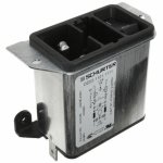
I've been on the hunt for the right power inlet module for this build. What I've been seeking is the C14 international standard plug, so anyone anywhere in any country could easily find the right power cord for it, with a built-in switch, a fuse (or dual fuse), shielded, EMI filtered, and most important, PCB mounted, for no wiring necessary.
What I found to be the most suitable so far, is from Schurter (posting a photo here). But that one is missing an important feature that I think is required for proper diy build anywhere out there, which is the built-in voltage selector, so it can properly switch the 110/220V with a dual primary winding transformer.
If anyone knows of a module that has all of the needed features, I'd like to know.
Features needed for the power inlet module:
- shielded
- EMI filtered
- fused
- switched
- C14 plug
- pcb mount
- voltage selection
- horizontal arrangement (for slim line build)
Attachments
Have a look on this video (in french), about an entirely adjustable Linkwitz transform based
on state variable filters :
Linkwitz et filtre a variable d’etat : mise en oeuvre | Jipihorn's Blog
Schematics : https://jipihorn.files.wordpress.com/2013/06/linkwitz-variable-state.pdf
on state variable filters :
Linkwitz et filtre a variable d’etat : mise en oeuvre | Jipihorn's Blog
Schematics : https://jipihorn.files.wordpress.com/2013/06/linkwitz-variable-state.pdf
Interesting stuff. Nice to have some technical explanations.
But still making use of 2gang pots, and this is nowhere near a full blown 4th order 4ways setup.
So far, my sims for a 4ways state variable, with 4th order linkwitz curve, is "only" using 15 opams, for the filters only, which really isn't bad if compared to the same thing done with the sallen-key cells, which then can't be "adjustable" in frequency with simple resistor tweaking.
I've noticed (in sims) how the component values can cause some deviations from the wanted result. So the choice of values is important and then I would systematically do actual parts matching in sets to make sure, even if using good tolerance parts.
Using parts with good tolerance already helps keeping the values somewhat close to the wanted ones, but then matching in sets further helps, even if not exactly as calculated.
I've been thinking about using the OPA2134 opamps. At first I thought the 4134 would be usable, with 4 opamps in one case, but they stopped making the DIP and only sell the SMTs now. At least, for now, the 2134 seems still available in DIP.
Have a look on this video (in french), about an entirely adjustable Linkwitz transform based
on state variable filters
Linkwitz correction can be implemented as an intrinsic part of a state-variable crossover by the use of weighted summing of filter outputs.
Regards
Charles
- Status
- This old topic is closed. If you want to reopen this topic, contact a moderator using the "Report Post" button.
- Home
- Loudspeakers
- Multi-Way
- State Variable Filter