Hi!!
I want to improve my 3-way speakers since I damaged the tweeter of one of them.
I opened the speakers enclosure and I was so disapointed with the crossover
Electrolitic capacitors and small inductors.
So I decided to do some improvements to the speaker system:
- [DONE] change both tweeters (dome) with new ones (Audax TW010F1) . Since the audax tweeter is not a silk dome like the originals, i have to upper a little the second crossover frequency.
- build an entire new crossover network, with decent inductors and capacitors
I started looking for the small/thielle parameters for each driver but I was unable to find them. So I decided to measure them using this guide:
http://sound.westhost.com/tsp.htm
I got the Fs, but I cannot continue measuring because I dont know what is Is, and the page didnt says.
So, if anyone can help me, I have a few questions.
1- what is "Is"? (look at the excel screenshot)
2- what do you think about the driver?
3- both "subwoofer" and "mid" are the same driver. Is that OK ??
I want to improve my 3-way speakers since I damaged the tweeter of one of them.
I opened the speakers enclosure and I was so disapointed with the crossover
Electrolitic capacitors and small inductors.
An externally hosted image should be here but it was not working when we last tested it.
So I decided to do some improvements to the speaker system:
- [DONE] change both tweeters (dome) with new ones (Audax TW010F1) . Since the audax tweeter is not a silk dome like the originals, i have to upper a little the second crossover frequency.
- build an entire new crossover network, with decent inductors and capacitors
I started looking for the small/thielle parameters for each driver but I was unable to find them. So I decided to measure them using this guide:
http://sound.westhost.com/tsp.htm
I got the Fs, but I cannot continue measuring because I dont know what is Is, and the page didnt says.
An externally hosted image should be here but it was not working when we last tested it.
So, if anyone can help me, I have a few questions.
1- what is "Is"? (look at the excel screenshot)
2- what do you think about the driver?
3- both "subwoofer" and "mid" are the same driver. Is that OK ??
some pics
An externally hosted image should be here but it was not working when we last tested it.
An externally hosted image should be here but it was not working when we last tested it.
An externally hosted image should be here but it was not working when we last tested it.
An externally hosted image should be here but it was not working when we last tested it.
An externally hosted image should be here but it was not working when we last tested it.
An externally hosted image should be here but it was not working when we last tested it.
hello.
holiday...............sitting in the garden (and drinking water or so)........
i am no speaker expert,but
have a look at figure 6 in the text.................
rs = 10 ohm
vref = voltage drop in the linear region above resonant frequency fs (in your diagram around 200.......300Hz; and between 10 and 20Hz)
and Is should be vref/rs (by ohm's law).
the driver has a high fs for a woofer...............no real "deep bass" if your measurement is well done.
looks like this is an "two and a half way sytem" (woofer and woofer-midrange).
have you drawn a schematic of the original network?
perhaps you do not need all this parameters because you have a box with it's speakers - so you only need to upgrade the parts and adapt the network for the tweeter................
greetings...............
Right...zafira1981 said:why nobody answer my post?I need some help, and there are lot of you that can help me!!

http://www.diyaudio.com/forums/showthread.php?postid=1843565#post1843565
mjf said:hello.
holiday...............sitting in the garden (and drinking water or so)........
i am no speaker expert,but
have a look at figure 6 in the text.................
rs = 10 ohm
vref = voltage drop in the linear region above resonant frequency fs (in your diagram around 200.......300Hz; and between 10 and 20Hz)
and Is should be vref/rs (by ohm's law).
the driver has a high fs for a woofer...............no real "deep bass" if your measurement is well done.
looks like this is an "two and a half way sytem" (woofer and woofer-midrange).
have you drawn a schematic of the original network?
perhaps you do not need all this parameters because you have a box with it's speakers - so you only need to upgrade the parts and adapt the network for the tweeter................
greetings...............
thank you very much, I've figured out how to do it.
I have a new question.
I want to connect a zobel network in the speaker, but according to this page http://sound.westhost.com/lr-passive.htm I have to know the inductance of the voice coil, wich I dont know. Using the excel spreadsheet I know the RLC parallel values of R, L and C, but I dont know the R and L series (I supose that L series is what I need)
An externally hosted image should be here but it was not working when we last tested it.
my question is how to find the L series, and if it is the one that should I use for the calc of the zobel network.
thanks!!!
hello.
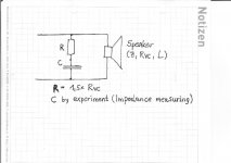
there is annother way to determine a rc network to compensate the increasing impedance in the upper frequency region.........
by experiment and measuring:
first measure the coil res (rvc) with a dmm(ohmmeter).
r in the zobel network should be around 50% bigger than rvc:
r = 1,5 x rvc
(powerrating a few watt).
and second try to find a cap that makes the impedance flat........
i would begin with 10uf (non polar elco) in your case.
build the network onto the speaker and measure the impedance........
change the value of the cap a little bit if it does not fit to find the flattest impedance curve............
greetings............
Attachments
- Status
- This old topic is closed. If you want to reopen this topic, contact a moderator using the "Report Post" button.
- Home
- Loudspeakers
- Multi-Way
- modding Yamaha NS-150. Measuring small-thiele parameters & new crossover