In this thread I am going to demonstrate how to create a convincing soundstage using waveguides and psychoacoustics. This thread will cover the construction of a loudspeaker in a car. However the experts on this subject rarely participate in car audio forums, so I'm going to delve into the subject here. (Hopefully the moderators don't mind.)
Here's some background on the project.
Some people may have seen my Unity horn projects, which were also in the car. Recently I attempted to take some of the "unity goodness" and scale it down. Unfortunately, it was not physically possible to do this, and I scrapped the project.
This new project will be similar to the last one. I'll be building an affordable, relatively accessible loudspeaker using waveguides.
This will not be as outrageous as my Unity horns, but it will also be a heck of a lot easier to build (hopefully!)
A number of people expressed interest in creating an excellent soundstage, but weren't willing to put Unities in the car.
So if you fall into that camp, this thread is for you. In addition, if you just want to learn some psychoacoustic "shortcuts" to create a good image, keep reading...
For a little background on my previous projects, which are all related, see these URLs:
Latest & Greatest :
http://www.diymobileaudio.com/forum/diy-mobile-audio/60146-creating-perfect-soundstage.html
The Unity from 2006:
http://audiogroupforum.com/csforum/showthread.php?t=62789
A lot of good discussion on Unities and waveguides:
http://www.diyaudio.com/forums/showthread.php?s=&threadid=117537&perpage=25&pagenumber=1
The most recent attempt at an "accessible" alternative:
http://www.diyaudio.com/forums/showthread.php?threadid=147568&goto=newpost
Like a lot of my car projects, this one is heavily based on the waveguide work done by USD audio. In a typical USD audio setup, there are horn-loaded compression drivers under the dash, midbasses up front or in the quarter panels, and subs in the trunk.
IMHO, the main reason to use horn-loaded compression drivers in the car is that it gives you enormous dynamics and it "equalizes" the path lengths.
For instance, if you put speakers in the door of your car, the pathlength difference between the left and the right will be a couple feet. With a waveguide under the dash the pathlength difference can be as little as 4" or so. That's the trick - it creates a center image by pushing the speakers very VERY far back.
Here's a picture from USD's web site of the mold for the horn in what is likely the best-known installation in the history of car stereo competition:

This project will use a similar configuration. Instead of an uber-expensive compression driver, I'm going to find out if we can get comparable results using more practical components.
IMHO, the main reason to use horn-loaded compression drivers in the car is that it gives you enormous dynamics and it "equalizes" the path lengths.
For instance, if you put speakers in the door of your car, the pathlength difference between the left and the right will be a couple feet. With a waveguide under the dash the pathlength difference can be as little as 4" or so. That's the trick - it creates a center image by pushing the speakers very VERY far back.
Here's a picture from USD's web site of the mold for the horn in what is likely the best-known installation in the history of car stereo competition:
This project will use a similar configuration. Instead of an uber-expensive compression driver, I'm going to find out if we can get comparable results using more practical components.
When people use waveguides in their car, they often have two common complaints. The first is that the soundstage is too low. The second is that the soundstage is too narrow.
There's a few things that can be done to fix this:
In this thread I'll explore an alternative. We'll leverage recent pyschoacoustic discoveries to seperate the frequency range.
In other words, we'll use two waveguides, physically seperated, with a waveguide for the midrange and a waveguide for the treble.
It's not as elegant as the Unity horn, but a heck of a lot easier to build (and hide.)
There's a few things that can be done to fix this:
- Move the waveguides onto the dash, a la my Unity horn project
- Mount the waveguides under the dash, but point them up. This is met with limited success; it's still easy to tell the stage is low.
- Modify the frequency response to 'fool' the listener. Also an improvement, but with limited success.
In this thread I'll explore an alternative. We'll leverage recent pyschoacoustic discoveries to seperate the frequency range.
In other words, we'll use two waveguides, physically seperated, with a waveguide for the midrange and a waveguide for the treble.
It's not as elegant as the Unity horn, but a heck of a lot easier to build (and hide.)
According to "Spatial Hearing"*, The opinion of the overwhelming majority of authors on this subject is that interaural time differences are the most important attributes of the ear input signals relating to the formation of lateral displacements of auditory events.
This single fact is why equalizing the path lengths is so effective in creating a phantom center channel in the car.
While this is well known, and frequently exploited in numerous winning designs, many find that the treble is lacking. The soundstage is too low, or the high frequencies suffer from audible colorations.
In the past few years there's been significant research into these hearing mechanisms, and mounting evidence that interaural time delays are virtually irrelevant above 1600hz.
For example, on page 172 of Spatial Hearing we find that "for signals with components above 1.6khz, the intensity image may dominate even when there are also low frequency components." (italics mine)
This aspect of hearing is why the left and right channel must match above 1600hz. Even a small difference in intensity will disturb the soundstage.
Yet ironically, it is the range about 1600hz that's prone to reflections in an automotive environment.
So we will get that range above the dash, where reflections are minimized, while minimizing pathlength differences via waveguides under the dash.
* Spatial Hearing, By Jens Blauert, John S. Allen
I've finished the plans for a midrange horn which will go under the dash. It was a lot more work than a tweeter horn, because it's a challenge to get flat response with such an under-sized horn.
In my previous designs I've used the dash to extend the curve, but since we're going UNDER the dash, we don't have that luxury. The dash WILL help extend the low end a bit, but nowhere near as much as when you couple with the windshield and the dash.
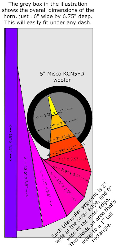
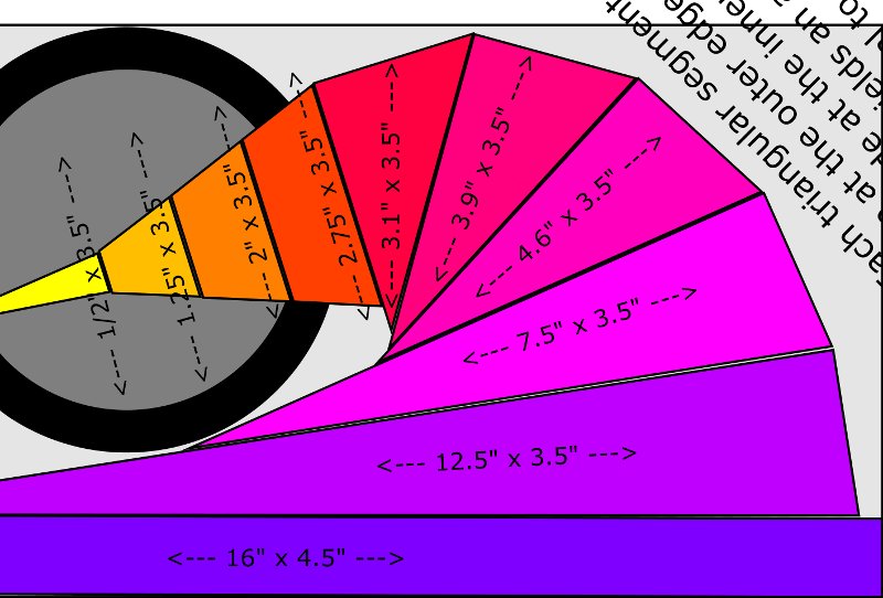
The number one goal of this design is to push the midranges back as far as possible, to equalize the left and the right pathlength. Based on that goal, I managed to cram a 500hz horn into a depth of just 6.75"!
I literally spent hours juggling the numbers, this is one of the trickiest horns I've ever made. When it's finished it will look a lot like a USD waveguide, but with a midrange where the compression driver normally goes. Here's a pic of mine:
Here's an illustration of the horn:
In my previous designs I've used the dash to extend the curve, but since we're going UNDER the dash, we don't have that luxury. The dash WILL help extend the low end a bit, but nowhere near as much as when you couple with the windshield and the dash.
The number one goal of this design is to push the midranges back as far as possible, to equalize the left and the right pathlength. Based on that goal, I managed to cram a 500hz horn into a depth of just 6.75"!
I literally spent hours juggling the numbers, this is one of the trickiest horns I've ever made. When it's finished it will look a lot like a USD waveguide, but with a midrange where the compression driver normally goes. Here's a pic of mine:
Here's an illustration of the horn:
Here is a "printable" version of the horn plans from above.
Basically print it out on your printer, transfer the shape to wood, and make sawdust.
To make it fit in 8" x 10", I had to cut out some parts, but it should be obvious if you look at the previous pic.
The height of the horn is 3.5" internally, except at the mouth. At the mouth it flares to 16" wide x 4.5" tall. The dimensions of each segment are printed in the illustration.
I will post horn response simulations shortly, and pics of the actual horn.
most current horn guys... well those who go about using current best practices in a car.. well tell you to get them as low and and wide under the dash as you can... to use the dash as an extension of the guide and to get the motor as wide as you can... most strive to get the motors to tuck into the kick panel cavity
trusound said:most current horn guys... well those who go about using current best practices in a car.. well tell you to get them as low and and wide under the dash as you can... to use the dash as an extension of the guide and to get the motor as wide as you can... most strive to get the motors to tuck into the kick panel cavity
Hopefully we can best the "state of the art."
Pushing the horns back increases the path length. That increases stage depth, and makes the phantom center "more solid."
Some things that we'll do here to improve upon the state of the art include:
- We'll use Geddes-style reticulated foam to reduce higher order modes. This is important in a waveguide, but even more so in a horn. A waveguide reduces HOMs by carefully reducing diffraction. Our horns, due to their contour, will have higher diffraction than a waveguide. Therefore, the foam is particularly important.
- Due to reflections and diffraction, it isn't possible to make a horn sound like the sound source is at the throat. Typically the sound appears to emanate at a point near the mouth. But the aforementioned technology should improve the impulse response to a point that the soundstage is much deeper than we're accustomed to in a car.
- Because this is a midrange horn, not a compression driver, we should play an octave lower than what is possible with even the best compression drivers. Of course we're sacrificing extension to get there.
OK, don't bother making the waveguide I posted a couple days ago, it doesn't fit.
Basically it gets in the way of the clutch pedal. It might work OK if you drive an automatic.
So I went back to the drawing board, and came up with a 70.56 x 18.92 degree conical waveguide. I didn't even bother with a CAD drawing, just created a mold and glassed it.
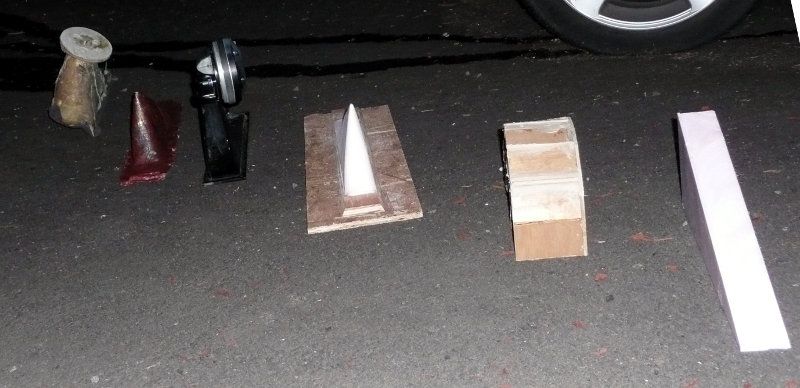
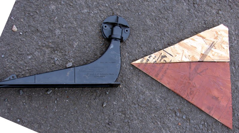
From left to right, there's a tractrix horn from my 2003 project, the new waveguide described above, a USD audio waveguide with a Radian 450PB compression driver, a mold for the new waveguide, the horn that I published two days ago, and a hunk of foam which was whittled down to create the waveguide mold.
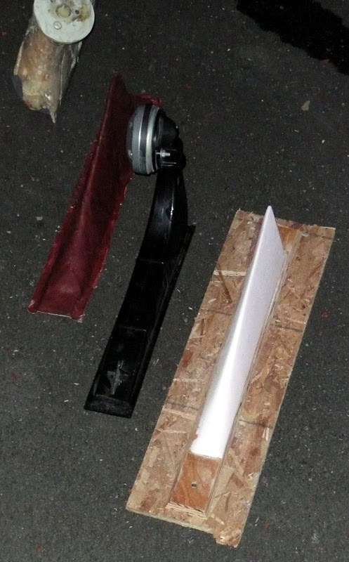
On the right is the new waveguide mold, in the middle is the USD waveguide.
The new mold looks a lot like this:
Basically it gets in the way of the clutch pedal. It might work OK if you drive an automatic.
So I went back to the drawing board, and came up with a 70.56 x 18.92 degree conical waveguide. I didn't even bother with a CAD drawing, just created a mold and glassed it.
From left to right, there's a tractrix horn from my 2003 project, the new waveguide described above, a USD audio waveguide with a Radian 450PB compression driver, a mold for the new waveguide, the horn that I published two days ago, and a hunk of foam which was whittled down to create the waveguide mold.
On the right is the new waveguide mold, in the middle is the USD waveguide.
The new mold looks a lot like this:
An externally hosted image should be here but it was not working when we last tested it.
I didn't think a horn that tall would fit under the dash of most cars and be easy to drive.
How high are you trying to go with this horn? Seems like you would want a supertweeter on the topend. Tall horns in a car have poor treble response. Another reason that I am asking if strictly midrange, the foam may or may not benefit greatly. I would guess in the 4-6k range is helped the most with the foam.
How high are you trying to go with this horn? Seems like you would want a supertweeter on the topend. Tall horns in a car have poor treble response. Another reason that I am asking if strictly midrange, the foam may or may not benefit greatly. I would guess in the 4-6k range is helped the most with the foam.
winslow said:I didn't think a horn that tall would fit under the dash of most cars and be easy to drive.
Ironically I could squeeze a horn that's 12" deep under the dash. The problem wasn't the depth, it was the area near the center, which interfered with the clutch pedal.
So I had two options. Either a 12" deep waveguide, with a very narrow mouth. Or a shallow waveguide, with an extremely wide mouth.
I went with option 2. There's an AES study that demonstrates that shallow horns sound better, and I'm inclined to believe that a shallow waveguide will also.
Ideally we would use a narrower waveguide, but the problem with a narrow waveguide is that the frequency response gets ragged as the volume of the waveguide is reduced.
This is just basic horn physics, the smaller the horn, the rougher the response.
winslow said:How high are you trying to go with this horn? Seems like you would want a supertweeter on the topend. Tall horns in a car have poor treble response. Another reason that I am asking if strictly midrange, the foam may or may not benefit greatly. I would guess in the 4-6k range is helped the most with the foam.
That's the wildest part of this project. These aren't treble horns; these are midrange horns.
USD Audio in California started the horn craze in the car audio world over twenty years ago. Back in the 80s there wasn't any way for a hobbyist to simulate a horn. The closest we could get were articles in Speaker Builder, by Bruce Edgar.
Because there was no way to simulate a horn, all you could do was follow "best practices" and hope for the best.
So if this was 1989, and we wanted to put a horn in a car, we'd probably load it with a compression driver.
USD uses Radian compression drivers, and considering that their factory is two blocks away, it seems like a smart choice. (They're also excellent and affordable.)
But this is 2009, and thanks to the wonders of Akabak and Hornresp, we can do some crazy things with horns which were simply impossible twenty years ago.
In particular, we can use a MASSIVELY undersized waveguide, one that's insanely small, by juggling all the parameters to smooth the response. According to my sims, it will only cover two and a half octaves. But it will play high enough to meet the tweeter, and low enough to reach the midbass. More importantly, it will have the efficiency of a compression driver and possibly smoother response. Oh and it's under $30
")
If someone can show me a pair of midranges that will hit 126DB with 100 watts, I'm all ears. The fact they're cheap is just a bonus.
Here's the graph:
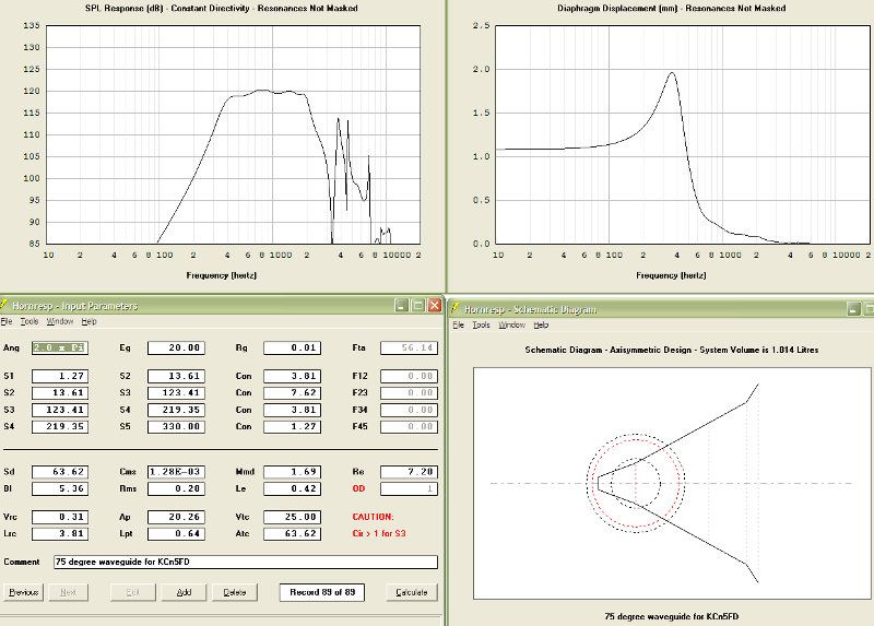
The midrange horn is the "secret sauce" in this project, we're basically going to find out if we can pound a square peg into a round hole.
In the previous post I mentioned Dr Bruce Edgar. Readers of this thread can download Edgar's articles here:
http://www.volvotreter.de/dl-section.htm
Here's another set of horns, this time from Image Dynamics:

By some kind of cosmic coincidence, the offices of Edgarhorn are on the same block as Image Dynamics. Odd.
http://www.enjoythemusic.com/magazine/equipment/0300/edgarhornslimline.htm
http://www.volvotreter.de/dl-section.htm
Here's another set of horns, this time from Image Dynamics:
By some kind of cosmic coincidence, the offices of Edgarhorn are on the same block as Image Dynamics. Odd.
http://www.enjoythemusic.com/magazine/equipment/0300/edgarhornslimline.htm
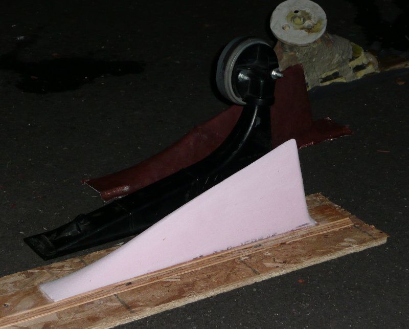
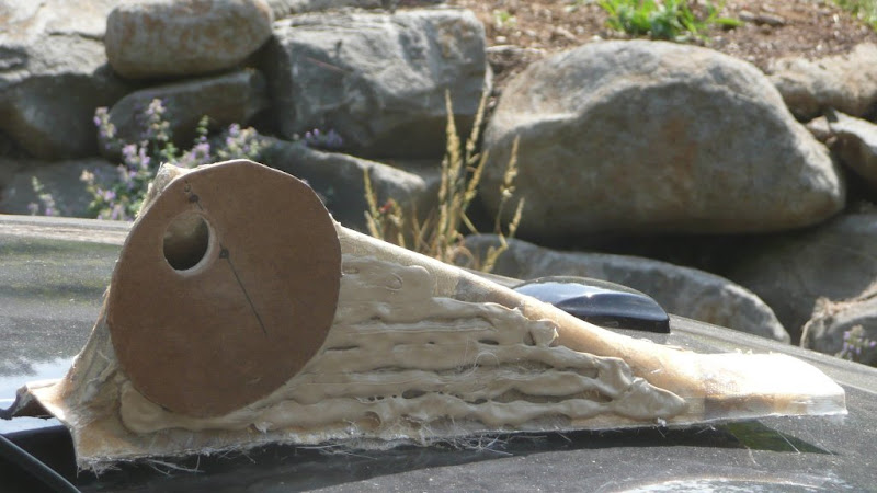
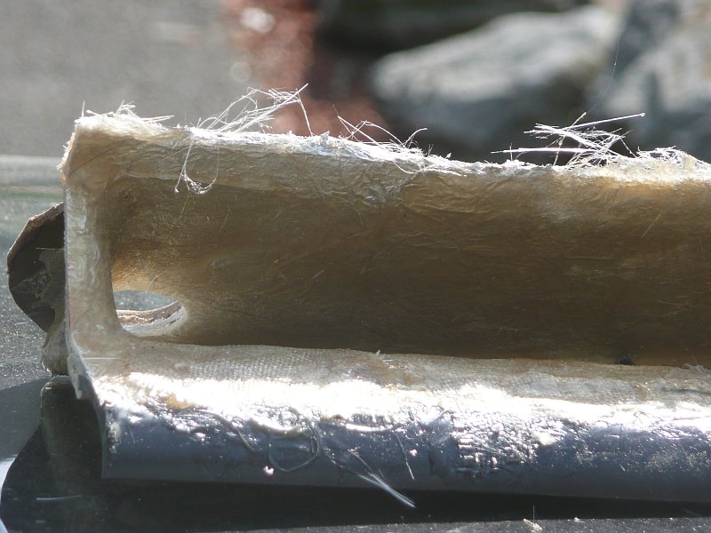
The waveguide is coming together nicely.
Shark fin mold on the left, waveguide on the right. The wood circle is where the midrange mounts on the waveguide.
I can't stress how important the location, depth, width and spacing of the holes are. If anyone following this thread tries to build one of these, be sure to get this part right.
Here's the deal:
The woofer isn't located at the throat, it's off center. In fact there isn't even a throat, it's a shark fin LOL
Get out a ruler, and make a mark one and a half inches from the apex. After you do that, drill four holes, each one 3/4" inches from the point you drew.
If you used a single hole, there would be a deep null at one-quarter wavelength from where you made that mark. For instance, with a mark at 1.5", there's going to a null at 2250hz.
The reason that I'm using four holes instead of one is that it reduces the depth of that null, spreads it out, and smooths out the response.
The width and depth of the holes is even more important than the spacing of the holes. Wider holes yield more SPL, but reduce bandwidth, and also reduces the F3.
The waveguide's throat. I will fiberglass the inside soon.
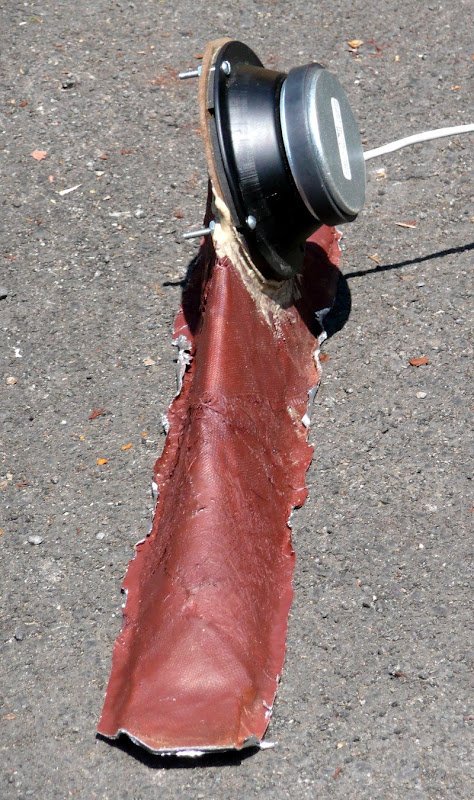
That's a Misco JC5RTF. The simulation is with a KCN5FD. Used the former because I still need to "seal up" the latter.
The waveguide has a much smaller footprint than a USD waveguide, because there's no throat.
Shark fin mold on the left, waveguide on the right. The wood circle is where the midrange mounts on the waveguide.
I can't stress how important the location, depth, width and spacing of the holes are. If anyone following this thread tries to build one of these, be sure to get this part right.
Here's the deal:
The woofer isn't located at the throat, it's off center. In fact there isn't even a throat, it's a shark fin LOL
Get out a ruler, and make a mark one and a half inches from the apex. After you do that, drill four holes, each one 3/4" inches from the point you drew.
If you used a single hole, there would be a deep null at one-quarter wavelength from where you made that mark. For instance, with a mark at 1.5", there's going to a null at 2250hz.
The reason that I'm using four holes instead of one is that it reduces the depth of that null, spreads it out, and smooths out the response.
The width and depth of the holes is even more important than the spacing of the holes. Wider holes yield more SPL, but reduce bandwidth, and also reduces the F3.
The waveguide's throat. I will fiberglass the inside soon.
That's a Misco JC5RTF. The simulation is with a KCN5FD. Used the former because I still need to "seal up" the latter.
The waveguide has a much smaller footprint than a USD waveguide, because there's no throat.
Patrick Bateman said:By some kind of cosmic coincidence, the offices of Edgarhorn are on the same block as Image Dynamics. Odd.
Actually they're in the same building and share a space last I was there (a few years ago).
In case anyone's following this, I am still working on it. I'm having some issues with frequency response which are driving me completely nuts tho
Basically there is a six db peak at 900hz, and a dip at 1800hz. Due to the synchronicity between the peak and the dip, it's likely due to a reflection of some sort. These are my theories:
Basically there is a six db peak at 900hz, and a dip at 1800hz. Due to the synchronicity between the peak and the dip, it's likely due to a reflection of some sort. These are my theories:
- one quarter wavelength of 900hz is 3.75". This may correspond to the height of the horn's mouth, which is about three inches, plus a baffle. To reduce the peak and the dip, I added a 1" roundover to the top half of the mouth. I didn't bother with the bottom half, because I have to be cautious about making the mouth too big. (I still have to drive the car, right?) Unfortunately, the roundover didn't make much of a difference. Keep in mind that the dash is already curved, and my measurements are being done inside the car. I think that's why the roundover didn't help much. If the baffle was flat, it would.
- A full wavelength at 900hz is 15". That's roughly the width of the horn. The fact that the height and the width are both resonating at the same frequency was an unfortunate coincidence. The solution to this would be to cut out a chunk of the waveguide to make it wider, perhaps 18". I could also narrow the mouth temporarily by adding chunks of foam. I tried this and it made a small, but measurable difference. Didn't solve the problem entirely, but it make a coupld DB of difference.
- Just for the hell of it, I jammed a couple blocks of foam into the mouth, which are 3.75" square, to see if it would break up the peak at 900hz. This also made a small difference, similar to the previous note.
- Just for the hell of it, I replaced the sealed back midrange with an open back midrange of the same type, just to see how it would measure. It actually measured quite well. It didn't elminate the peak and the dip, but it smoothed things out quite a bit. I don't think I'll go this route because you can hear that the midrange is struggling due to excursion, and it makes the horn VERY directional, due to interference from front to back.
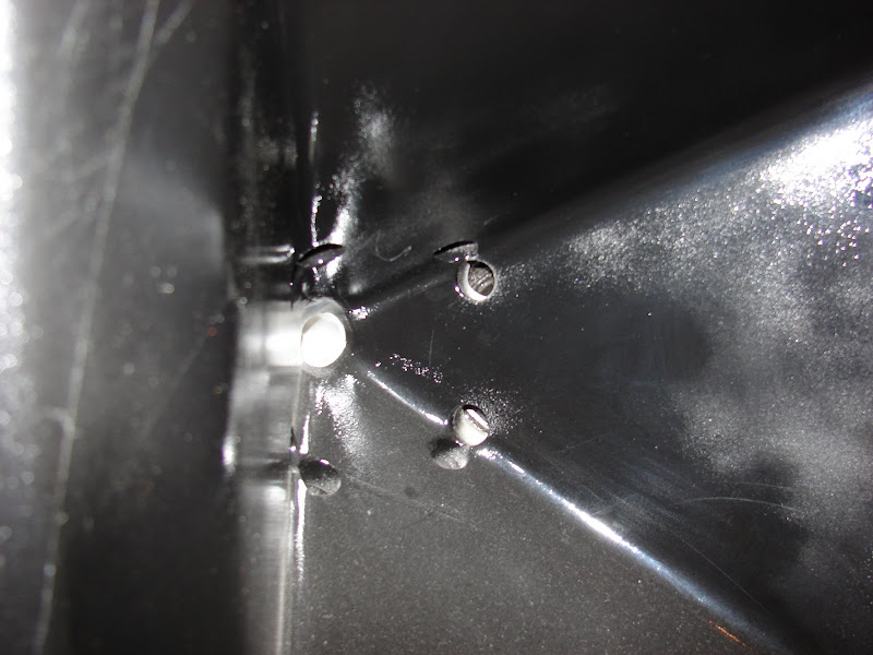
- The last option is the location of the midrange. According to theory, there should be a HUGE null which corresponds to 1/4 wavelength from the throat to where the midranges enter the horn. That's why I have four holes instead of one, to spread out that null. Here's a pic:
At this point I'm wondering if the four holes are working like I'd hoped they'd work. According to Akabak simulations, four holes should spread out the null from the reflection. But maybe it isn't working. The fourth hole is located about four inches from the throat, which corresponds to 844hz. That could be what's causing our null.
To find out for certain, I've started to build the second waveguide. For the second waveguide, I am going to drill the holes MUCH closer to the throat. The midrange is still located off-axis, but the holes will be located right at the edges of the horn, instead of symmetrically. Here's a pic of a Unity horn, to give you an idea of what I'm talking about.
I wanted to "dive in" to the subject of psychoacoustics today.
Our hearing mechanism behaves differently at high and low frequencies; there is a transition point around 1khz. Above that frequency, we're very sensitive to frequency response. But not particularly sensitive to location. Below this frequency, we're very sensitive to location, but frequency response is less of an issue. In the midrange, they're both important.
If you've ever listened to a typical horn speaker, and noted that it didn't image well, you've experienced this. Due to reflections and the shape of the horn, typical horns "beam" at high frequencies. This beaming causes the frequency response to vary dramatically as you move even an inch or two off axis.
On the flip side, the reason that mini-monitors image so well is that they're isn't a whole lot to reflect off of; with a minimum of reflections due to their tiny cabinets, they're champs at imaging.
For additional info on this, check out the first page of the thread.
Another thing about imaging, is that there's little improvement to be made with DSP. For instance, a time delay on your midranges may improve the intelligibility of your stereo, or the frequency response. But your brain will always be able to detect where the midranges are located. DSP can't fool you into thinking they are somewhere else.
That's the main reason I am using horns in this project. It's not for directivity control (though that's a part.) And it's not to increase the efficiency. I am using horns to get the woofers as far back as humanly possible. With the current horns, the basket of the woofer is pressed right up against the firewall of the car. That's further back than you can get with a kick panel, where the woofer is 6-12" closer to the listener.
I hope that makes sense. We're splitting the frequency range right down the middle. Above the midrange, the goal will be flat and consistent frequency response, on axis and off. Below the midrange, the distance, location and pathlength are paramount.
Ideally, we'd use two drivers. One to cover 20-1500hz, and one to cover 1.5-20khz. Unfortunately, you're not going to get a horn to cover six octave. So I'm compromising, and trying to squeeze two and a half octaves out of my horns.
The goal is to cover 350hz to 2khz, then hand off to a tweeter that's located at eye level.
Here are polar measurements of the horn that I did today.
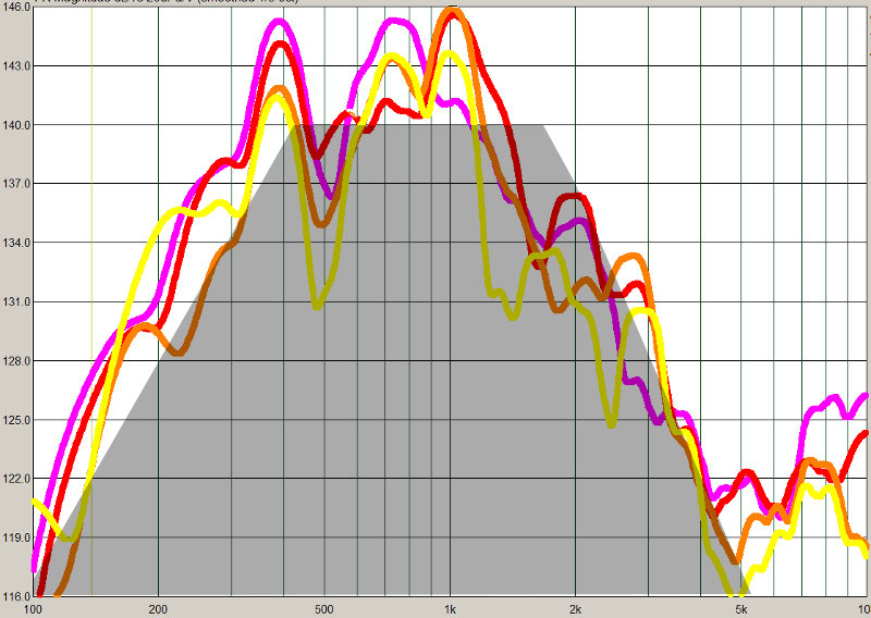
The grey area is the goal - flat response from 350 to 2000hz, with a 2nd order rolloff on each side.
The purple trace is on axis. Red, Orange, and yellow are 15, 30, and 45 degrees off axis.
Here are my thoughts on the measurements:
Our hearing mechanism behaves differently at high and low frequencies; there is a transition point around 1khz. Above that frequency, we're very sensitive to frequency response. But not particularly sensitive to location. Below this frequency, we're very sensitive to location, but frequency response is less of an issue. In the midrange, they're both important.
If you've ever listened to a typical horn speaker, and noted that it didn't image well, you've experienced this. Due to reflections and the shape of the horn, typical horns "beam" at high frequencies. This beaming causes the frequency response to vary dramatically as you move even an inch or two off axis.
On the flip side, the reason that mini-monitors image so well is that they're isn't a whole lot to reflect off of; with a minimum of reflections due to their tiny cabinets, they're champs at imaging.
For additional info on this, check out the first page of the thread.
Another thing about imaging, is that there's little improvement to be made with DSP. For instance, a time delay on your midranges may improve the intelligibility of your stereo, or the frequency response. But your brain will always be able to detect where the midranges are located. DSP can't fool you into thinking they are somewhere else.
That's the main reason I am using horns in this project. It's not for directivity control (though that's a part.) And it's not to increase the efficiency. I am using horns to get the woofers as far back as humanly possible. With the current horns, the basket of the woofer is pressed right up against the firewall of the car. That's further back than you can get with a kick panel, where the woofer is 6-12" closer to the listener.
I hope that makes sense. We're splitting the frequency range right down the middle. Above the midrange, the goal will be flat and consistent frequency response, on axis and off. Below the midrange, the distance, location and pathlength are paramount.
Ideally, we'd use two drivers. One to cover 20-1500hz, and one to cover 1.5-20khz. Unfortunately, you're not going to get a horn to cover six octave. So I'm compromising, and trying to squeeze two and a half octaves out of my horns.
The goal is to cover 350hz to 2khz, then hand off to a tweeter that's located at eye level.
Here are polar measurements of the horn that I did today.
The grey area is the goal - flat response from 350 to 2000hz, with a 2nd order rolloff on each side.
The purple trace is on axis. Red, Orange, and yellow are 15, 30, and 45 degrees off axis.
Here are my thoughts on the measurements:
- If you're accustomed to seeing measurements in an anechoic chamber, these results will be frightening! But these were taken in the car, warts and all. It's a hostile environment.
- There's an ugly null at 500hz. That may be due to a reflection off the center console and the door. I can fix this with a bit of foam at the mouth.
- It's playing about an octave lower than the simulation predicted. Likely due to cabin gain.
- Like the model predicted, there's output above 5khz, but I can get rid of that with a crossover.
- The F3 at the top end is about 1500hz, half an octave lower than I'd hoped for. I am hoping that a bit of work at the throat will buy me another half an octave.
- For a car, these are excellent results IMHO. It is extraordinarily difficult to get off-axis measurements that track the on-axis measurements in a car. It's just a VERY hostile environment. The 0 and the 15 degree measurements track within 3db across the entire range, and the 30 and the 45 aren't far behind.
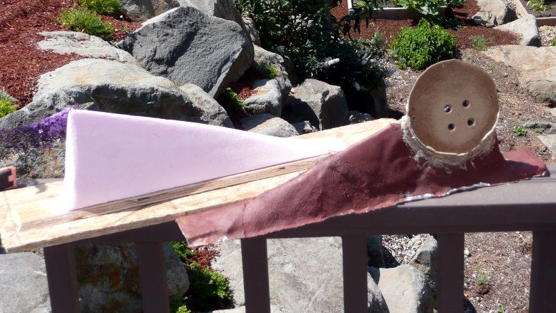
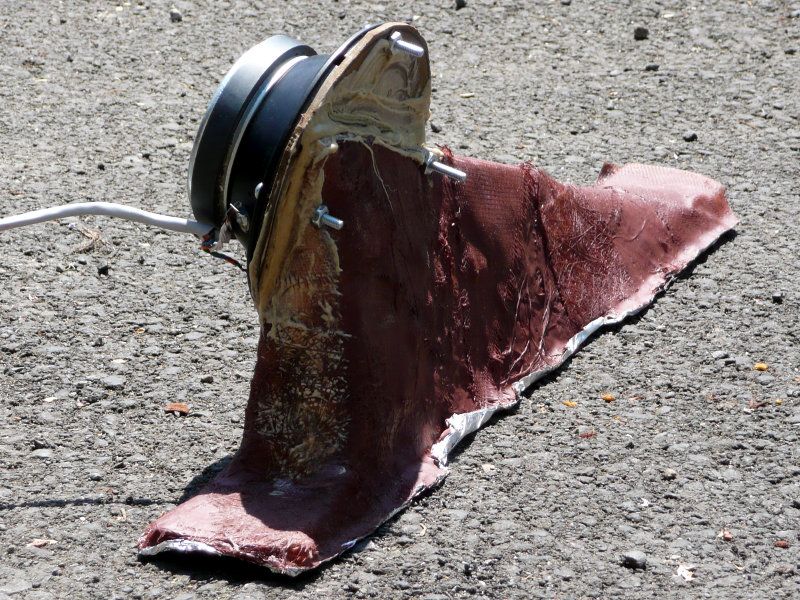
Here's a pic of the horn which I measured in the previous post.
If you compare this to the other horn, you'll notice a few things.
The throat is 1" across. In the previous horn there were four holes, each was 1/2" across. So the area is identical.
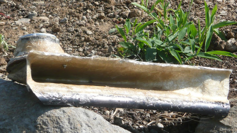
That's about 15" across. Still need to paint and finish it.
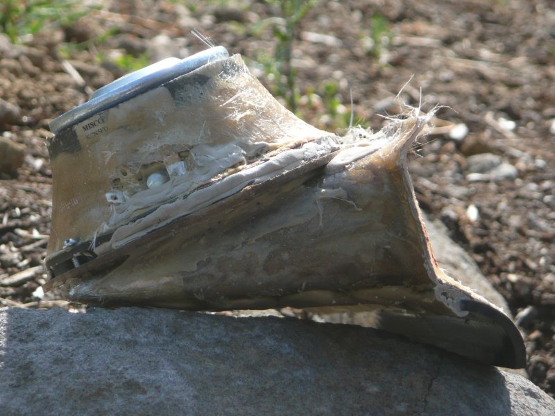
In the side view you can really see how shallow it is. The whole thing is just over six inches deep. That allows me to cram it waaaaay under the dash. Also, the midrange is completely mummified in fiberglass and clay, to seal the basket.
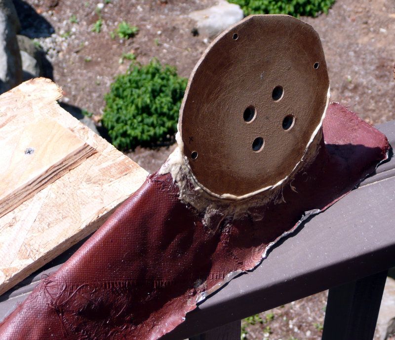
If you compare this to the other horn, you'll notice a few things.
- There's one hole instead of four. I'll explain why I did this in the next post.
- The midrange is much closer to the mouth of the horn. Note that the hole is still close to the back. The location of the midrange is practically irrelevant, it's the location of the throat that matters.
- Due to the shallower depth, I can push this all the way under the dash. You wouldn't want to do that with a tweeter, but since we're only playing up to 2khz, we can get away with this.
The throat is 1" across. In the previous horn there were four holes, each was 1/2" across. So the area is identical.
That's about 15" across. Still need to paint and finish it.
In the side view you can really see how shallow it is. The whole thing is just over six inches deep. That allows me to cram it waaaaay under the dash. Also, the midrange is completely mummified in fiberglass and clay, to seal the basket.
Last edited:
- Status
- This old topic is closed. If you want to reopen this topic, contact a moderator using the "Report Post" button.
- Home
- Loudspeakers
- Multi-Way
- Creating a Soundstage with Waveguides and Psychoacoustics