Hmm, if you modeled mine, then I wonder why it doesn't match it.
Mine's already billiard table flat, so lengthening the vent will roll it off. If you mean my dims except with the driver at the top, then 3" appears to be maximally flat.
Regardless, in the LF BW the room dominates, so this sort of 'splitting hairs' in basic sims is moot since these tunings may not be even close to what's needed in-room.
Right, with the driver-vent spaced as far apart as possible you get max 1/4 WL action, ie. max loading of the vent, so as you move the driver down the pipe both vent loading and pipe harmonics are reduced in amplitude. keeping the driver at the top and raising the vent causes a second set of resonances to be generated between the pipe floor and vent, so not my first choice, instead preferring to leave the vent near/at the bottom and either lengthen and/or damp it if required to smooth any perceived box 'boom' and/or audible ringing.
Sometimes though, moving the driver down and the vent up is a good choice to get a nice trade-off between smoothness/vent loading such as a party and/or vinyl era music speaker where you want that vintage 'toe tapping'/acoustic BSC 'sound'. The roll off below Fb is steeper, but if tuned to < ~42 Hz it works fine such BW limited apps.
WRT the driver being physically down 20% usually being anywhere near the optimum point, in my experience it's almost never the case based on my proprietary way of calculating it and my opinion as to what 'optimum' constitutes since it's a function of line length and CSA, though MJK's probably much more math intensive way to find it may be the more technically correct ones as listed in his Classic TL designer, but never having compared the two I don't know if there's any audible difference and/or if there is, whether or not one sounds better/more accurate.
Anyway, the gentle reader might want to give MJK's driver location specs combined with a low stuffing density a try on your next MLTL experiment/build. Worst case is you'll have to add more stuffing if not happy with it.
GM
Martin made some very significant changes between his old free worksheets and the first release of his subcription-based worksheets. Since I use his latest worksheets I suspect those improvements cause my modeling of your cabinet (using the exact dimensions for everything you listed including the driver being 18+ inches down from the top) to have a bit of a rise in the response at the low end, thus needing a bit lower tuning frequency. Of course I could be wrong.
I, too, have found that moving the driver and/or the vent towards each other can have some very obvious benefits in smoothing the overall response. Usually I'm kinda stuck, for various reasons, with a specific driver location and have to limit my experiments with vent movements. I have an entirely open mind, within whatever criteria might be imposed on a particular design that limits my options, on locating the driver and vent but I haven't ever tried placing the driver at ~45% down the line like yours is.
As to using lighter stuffing densities, I will consider them but only as long as my personal criteria on overall response smoothness is satisfied.
GM said:Hmm, if you modeled mine, then I wonder why it doesn't match it.
Mine's already billiard table flat, so lengthening the vent will roll it off. If you mean my dims except with the driver at the top, then 3" appears to be maximally flat.
Regardless, in the LF BW the room dominates, so this sort of 'splitting hairs' in basic sims is moot since these tunings may not be even close to what's needed in-room.
Right, with the driver-vent spaced as far apart as possible you get max 1/4 WL action, ie. max loading of the vent, so as you move the driver down the pipe both vent loading and pipe harmonics are reduced in amplitude. keeping the driver at the top and raising the vent causes a second set of resonances to be generated between the pipe floor and vent, so not my first choice, instead preferring to leave the vent near/at the bottom and either lengthen and/or damp it if required to smooth any perceived box 'boom' and/or audible ringing.
Sometimes though, moving the driver down and the vent up is a good choice to get a nice trade-off between smoothness/vent loading such as a party and/or vinyl era music speaker where you want that vintage 'toe tapping'/acoustic BSC 'sound'. The roll off below Fb is steeper, but if tuned to < ~42 Hz it works fine such BW limited apps.
WRT the driver being physically down 20% usually being anywhere near the optimum point, in my experience it's almost never the case based on my proprietary way of calculating it and my opinion as to what 'optimum' constitutes since it's a function of line length and CSA, though MJK's probably much more math intensive way to find it may be the more technically correct ones as listed in his Classic TL designer, but never having compared the two I don't know if there's any audible difference and/or if there is, whether or not one sounds better/more accurate.
Anyway, the gentle reader might want to give MJK's driver location specs combined with a low stuffing density a try on your next MLTL experiment/build. Worst case is you'll have to add more stuffing if not happy with it.
GM
30 Hz MLTL with driver 0.349*L = ~14.135". Not quite as smooth overall compared to my suggested location, but I doubt it would be audible and if nothing else puts it closer to the mid/HF horn perched on top. Really, all things considered, this cab is acoustically large enough that I imagine none of the suggested alignments/driver locations have any sonic in-room advantage beyond the distance between the drivers Vs the XO point/slope and stuffing density required to smooth it all out.
GM
GM
Attachments
pkitt said:
Since I use his latest worksheets.........
OK, I used rev. 2.9.08 which is the most current one listed on his website as of yesterday, so have you got something different that I apparently don't have access to? Or did we use different unpublished, ergo calc'd, specs such as BL, Sd? I used 17.4083 N/A, 847.308 cm^2.
GM
Zen Mod said:boyz - while you are eager to discuss , may I ( humble , as always) ask you for one quickie sim ....... ?
I can't do anything with old free Martin's sheets - that old 8" FR driver is near 100db/W/m and I'm having just mess results ......
??? I assume you're referring to another thread and if not, please start one in the appropriate forum with all the pertinent details.
GM
GM said:
??? I assume you're referring to another thread and if not, please start one in the appropriate forum with all the pertinent details.
GM
yes Sir
")
edit :
http://www.diyaudio.com/forums/showthread.php?postid=1833717#post1833717
I used the T/S values provided by the OP: Fs=22.9, Re=6.55, Le=0.37, Bl=17.7, Sd=845, Vas=693, Qes=0.22 and Qms=6.7. It appears there are some minor differences compared to what you used and perhaps that caused the different modeling results. We are using the same version of worksheet from Martin by date. I'm using the ML-TQWT worksheet and even if you used the vented box worksheet, we should get the same results for the same input data.
GM said:
OK, I used rev. 2.9.08 which is the most current one listed on his website as of yesterday, so have you got something different that I apparently don't have access to? Or did we use different unpublished, ergo calc'd, specs such as BL, Sd? I used 17.4083 N/A, 847.308 cm^2.
GM
OK, I missed his followup post. When I use these specs I actually need to shorten the vent to make it maximally flat rather than longer, so I'm at a loss as to why our sims aren't identical except possibly for the fact that I never could get the earlier MLTQWT SS to exactly match to the PORTED one. Anyway, like I said it's inaudible/moot, so not going to waste any more time on it.
GM
GM
I agree the differences are insignificant but I remembered something Martin told me which may apply here. When I'm trying to find what kinds of TLs a specific driver might work well in, I use the ML-TQWT worksheet because it allows exact modeling for ML-TL and ML-TQWT, plus a very close to exact modeling for a tapered TL, assuming the tapered line has to be folded. But to get an exact model for a folded, tapered line I make a drawing, then model it with the Sections worksheet. You can, of course, model an ML-TL or ML-TQWT in the Sections worksheet, but if you do, you won't get results identical to those from the ML-TQWT worksheet. Martin told me his software applies an end-correction for the port tube when using the ML-TQWT worksheet but not when using the Sections worksheet and, maybe, at one time, that's why you weren't able to get identical results between the old ML-TQWT and Ported worksheets, assuming Martin didn't apply port end-corrections consistently across the worksheets. One more thought; I'm using the free version of MathCad and you're using the Professional version. Any chance there are some differences due to them?
GM said:OK, I missed his followup post. When I use these specs I actually need to shorten the vent to make it maximally flat rather than longer, so I'm at a loss as to why our sims aren't identical except possibly for the fact that I never could get the earlier MLTQWT SS to exactly match to the PORTED one. Anyway, like I said it's inaudible/moot, so not going to waste any more time on it.
GM
pkitt said:I agree the differences are insignificant but I remembered something Martin told me which may apply here. When I'm trying to find what kinds of TLs a specific driver might work well in, I use the ML-TQWT worksheet because it allows exact modeling for ML-TL and ML-TQWT, plus a very close to exact modeling for a tapered TL, assuming the tapered line has to be folded.
The later versions of the ML TQWT and Ported Box worksheets are the same, I just updated the default stuffing locations to be representative of the style of design. If you enter exactly the same inputs into each worksheet you will get exactly the same results.
The original versions of the ML TQWT (2002 - 2004) did not include the ability to move the port position along the line like the Ported Box worksheet, it was assumed that the port was an extension added to the end of the line. Sometime between 2004 and 2006 I upgraded the ML TQWT worksheet to include this capability.
Any worksheet with a user defined port has always contained an end correction at the inside end of the port tube to account for the acoustic impedance.
But to get an exact model for a folded, tapered line I make a drawing, then model it with the Sections worksheet. You can, of course, model an ML-TL or ML-TQWT in the Sections worksheet, but if you do, you won't get results identical to those from the ML-TQWT worksheet.
Exactly correct. If you want to model a fold in the ML TQWT or Ported Box worksheets you can by editting the default section definitions just like in the Sections worksheets.
Martin told me his software applies an end-correction for the port tube when using the ML-TQWT worksheet but not when using the Sections worksheet and, maybe, at one time, that's why you weren't able to get identical results between the old ML-TQWT and Ported worksheets, assuming Martin didn't apply port end-corrections consistently across the worksheets.
There should be differences between the Sections worksheet and the ML TQWT or Ported Box worksheets due to the end correction applied to the port. A port is assumed ot stick into the interior of the enclosure, the Sections worksheets assume each sections is added to the end of the previous section. Ports are also allowed to be placed along the line so that a "stub section" is created between the port and the end of the line. All ports have always included an end correction in my worksheets.
One more thought; I'm using the free version of MathCad and you're using the Professional version. Any chance there are some differences due to them?
All of the versions of MathCad should calculate the same result for a given worksheet. If you, Paul and GM, are getting slightly different results with the same version (date at the top right of first page) of a worksheet it is due to a slight difference in the inputs.
Hope that helps,
Hey, Martin...
Thanks for chiming in here and I hope my comments relative to your worksheets weren't out of line, causing you any upset. I have to conclude that the slightly different results GM and I got were due, in fact, to entering slightly different T/S values for the driver in question. I, and presumably GM, too, appreciate your input and clarifications.
Thanks for chiming in here and I hope my comments relative to your worksheets weren't out of line, causing you any upset. I have to conclude that the slightly different results GM and I got were due, in fact, to entering slightly different T/S values for the driver in question. I, and presumably GM, too, appreciate your input and clarifications.
Re: Hey, Martin...
No problem with your comments, no reason for concern. The only person who really knows what is in the worksheets is me, I tried to tell my wife once but she quickly tuned me out. I just did not want you and GM to waste any time wondering if it was an input or calculation difference. If your answers are close it is probably a very small difference in one input and not worth spending a lot of time chasing down.
pkitt said:Thanks for chiming in here and I hope my comments relative to your worksheets weren't out of line, causing you any upset. I have to conclude that the slightly different results GM and I got were due, in fact, to entering slightly different T/S values for the driver in question. I, and presumably GM, too, appreciate your input and clarifications.
No problem with your comments, no reason for concern. The only person who really knows what is in the worksheets is me, I tried to tell my wife once but she quickly tuned me out. I just did not want you and GM to waste any time wondering if it was an input or calculation difference. If your answers are close it is probably a very small difference in one input and not worth spending a lot of time chasing down.
question for both GM and pkitt :
did you boyz made this simulations using TSP from post one of the thread http://www.diyaudio.com/forums/multi-way/143784-help-mltl-design-gpa416-8c.html#post1823580 or with TSP for original old Altec 416-8C ?
reason for asking is that results of my sims with newest Martin's sheets aren't same as yours ....
hehe - I have slight impression that I'm making some mistake , but - it's better to ask ..... just in case .
TIA
It's been so long since I did the modeling that I can't remember which source of T/S values I used, and I didn't copy and save any of the modeling. Why don't you share what you've simmed using Martin's worksheets so we can easily see what you're seeing?
Paul
Paul
question for both GM and pkitt :
did you boyz made this simulations using TSP from post one of the thread http://www.diyaudio.com/forums/multi-way/143784-help-mltl-design-gpa416-8c.html#post1823580 or with TSP for original old Altec 416-8C ?
reason for asking is that results of my sims with newest Martin's sheets aren't same as yours ....
hehe - I have slight impression that I'm making some mistake , but - it's better to ask ..... just in case .
TIA
It's been so long since I did the modeling that I can't remember which source of T/S values I used, and I didn't copy and save any of the modeling. Why don't you share what you've simmed using Martin's worksheets so we can easily see what you're seeing?
Paul
sure ; I hope these two screenshots are enough
edit : box dimensions exactly as per GM's calc
Attachments
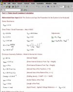
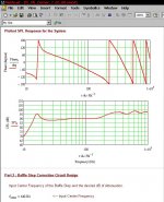
You might want to check your entries for So and Sl. You've got them both at 385.75 x 11 inches, which is about 32 feet x almost 1 foot! That's a might big box, don't you think?
Paul
Paul
sure ; I hope these two screenshots are enough
edit : box dimensions exactly as per GM's calc
You might want to check your entries for So and Sl. You've got them both at 385.75 x 11 inches, which is about 32 feet x almost 1 foot! That's a might big box, don't you think?
Paul

it's always better to have temporary short circ between ears , then any other glitch
tnx!
You might want to check your entries for So and Sl.
Rport also! I spec'd a 6" diameter port (dport), so rport = 3", at least for initial testing.
GM
- Status
- This old topic is closed. If you want to reopen this topic, contact a moderator using the "Report Post" button.
- Home
- Loudspeakers
- Multi-Way
- Help with MLTL design for GPA416-8c