Yep, the baffles are uglier - not by a whole lot.
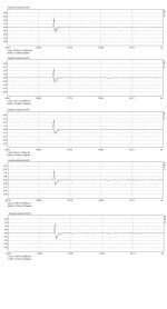
But - compared to the unbaffled muffler at 22.5 degrees, yes, they're worse. The way they settle down is lumpy and uneven, which is indicative of trouble of some kind. Most obvious guess is multipath, which has the unhappy property of being non-minimum phase.
I should add the 22.5~30 degree unbaffled muffler is really pretty good by any standard - that's pretty tidy decay performance (within electrostat territory). My guess is the wave coming from the rear is spread out in time sufficiently that it doesn't contribute to the comb-filtering we're seeing in the other graphs. Considering that deep comb-filtering is not really correctable by EQ, this is a good thing.
Good solid work, MBK. This is great data, and very informative!!!
Thanks for the flowers Lynn ") .
.
As I said above here I tried to compile a useful set of information first, with actual data, and to answer actual questions in an iterative way. So if it looks like a chock full at first, it's because it was intended to be comprehensive within its limited scope. And maybe it allows people interested in this approach to make at least some design decisions starting from this.
I'll be back with more whenever I get around it for a more fine tuned set of data, which may mean, weeks.
. As I said above here I tried to compile a useful set of information first, with actual data, and to answer actual questions in an iterative way. So if it looks like a chock full at first, it's because it was intended to be comprehensive within its limited scope. And maybe it allows people interested in this approach to make at least some design decisions starting from this.
I'll be back with more whenever I get around it for a more fine tuned set of data, which may mean, weeks.
I 1/2 agree with what Lynn is saying. But if you are truly after cardioid response the baffle size has to be considered as part of the puzzle. The driver mounted on the baffle will control where the front response becomes directional, i.e. the baffle step of a conventional sealed box system. Below the baffle step the driver/baffle is acting as an omnidirectional, 4Pi source, above a 2Pi source. When the rear wave is used to augment the front response to form a cardioid the rear must be LP filtered with a corner frequency somewhere in the range of the baffle step or 2Pi to 4Pi transition. Obviously, if the front radiation is confined to 2Pi then anything in that frequency range from the rear must be filtered so there is no rear radiation in that frequency range. In this frequency range diffraction is not different that normal diffraction and must be dealt with appropriately.
Below the baffle step the same LP filtering will delay the rear response compared to the front. The LP filtering must not significantly alter the amplitude of the rear low frequency radiation. If this is accomplished then when summed to the front low frequency response on axis will be a 1st order gradient response at low frequency instead of the typical baffle step. That is, it will continue to roll off at 6dB/octave rather that plateau at -6dB. From the rear and other off angle positions how the front and rear response sum will depend on the relative delays. That is, if the LP filter of the rear response introduces a 0.5msec delay at low frequency then the baffle must be sized so that the effective delay around the baffle from front to rear is also 0.5 msec. When this is accomplished AND the rear response at low frequency is of the same amplitude as the front response you will start to see cancellation of low frequency at the rear. The trick, if the driver is to be used over a wide frequency range, spanning the conventional baffle step, is to get this working all in unison over the required frequency range.
If the LP filtering adds too much flow resistance the low frequency from the rear will be attenuated in which case, depending of the degree of attenuation, the response will start to degenerate back to omnidirectional at low frequency.
As for the impulse, yes look at it, but you should look at if after the crossover filter and any other eq is in place. Thus, look at the impulse when the system is in a form that it will be used in the speaker. If the driver is going to be used over a limited bandpass then how it performs in the band pass is what needs to be investigated.
John,
no question, 3 things are at work, baffle size induced directionality and delay, flow resistance induced delay at the rear, and LP filtering of the rear. In my various tests I believe we see evidence of all the above:
- the baffle size experiments show how the "baffle step" (actually the dipole cutoff) is shifted lower with increasing size, while the dipole type -6 db/octave falloff persists regardless of baffle size;
- the closed side muffler shows how excessive rear wave LP filtering induces a shift back to closed box directivity;
- the small baffle ordinary muffler shows how a moderate and relatively "pure" flow resistance, with a fairly high frequency LP component, leads to a surprisingly good behavior with little effort in the intended passband (300-1500 Hz approximately).
- related to above and to your last point, making baffle size delays correspond with flow resistance induced delays to cancel just the rear wave, this clearly collapses below ca. 600 Hz in my setup, more so when using larger baffle sizes. The polars revert to figure-eight below ca. 600 Hz.
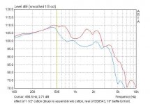
In the attached graph is an indication why - a comparison of rear nearfield output with and without the 1 1/2 " cotton of the muffler assembly (assembly in place for both curves, and 16" baffle used to avoid contamination by front wave). The cotton takes away about 8-12 dB but above 500 Hz only.
In my case this may not matter since I have a dipole bass waiting for crossover around 300 Hz, so I'll be quite OK if the pattern returns to dipole at those lower frequencies as long as the power response holds up, which it does according to Arta.
no question, 3 things are at work, baffle size induced directionality and delay, flow resistance induced delay at the rear, and LP filtering of the rear. In my various tests I believe we see evidence of all the above:
- the baffle size experiments show how the "baffle step" (actually the dipole cutoff) is shifted lower with increasing size, while the dipole type -6 db/octave falloff persists regardless of baffle size;
- the closed side muffler shows how excessive rear wave LP filtering induces a shift back to closed box directivity;
- the small baffle ordinary muffler shows how a moderate and relatively "pure" flow resistance, with a fairly high frequency LP component, leads to a surprisingly good behavior with little effort in the intended passband (300-1500 Hz approximately).
- related to above and to your last point, making baffle size delays correspond with flow resistance induced delays to cancel just the rear wave, this clearly collapses below ca. 600 Hz in my setup, more so when using larger baffle sizes. The polars revert to figure-eight below ca. 600 Hz.
In the attached graph is an indication why - a comparison of rear nearfield output with and without the 1 1/2 " cotton of the muffler assembly (assembly in place for both curves, and 16" baffle used to avoid contamination by front wave). The cotton takes away about 8-12 dB but above 500 Hz only.
In my case this may not matter since I have a dipole bass waiting for crossover around 300 Hz, so I'll be quite OK if the pattern returns to dipole at those lower frequencies as long as the power response holds up, which it does according to Arta.
Attachments
If you have a figure 8 polar patter then your LP filter isn't doing very much. With nominally 0 delay form the LP filter you end up with a dipole at low frequency. As the LP delay increases the nulls move rearward and eventually collapse to a cardioid. Like this:
An externally hosted image should be here but it was not working when we last tested it.
But John, that's exactly what is happening in my data:
- The LP has an effect roughly above 500-600 Hz (previous post), though the measurement was a one-off, not very clean and it was just a for the record exercise.
- The cardioid increasingly turns figure eight by around 600 Hz (post 13) . Post 11 has a sonogram to that effect.
We seem to be in violent agreement here...
hi!
happy to read something about cardiod ,because it's seems to be a very interesting radiating mode,and your datas are very instrutive MBK
thank you!
but i have a question,with your prototype,did you verify the theoric +6db or something like that,in cardiod mode vs "dipole like" mode,like described here ?
and since you mention it, do you think to try the gradient elsinky design,it's pretty close to yours,and baffle shape and tweeter coupling are pretty well thought !!
have a good day
MBK said:But John, that's exactly what is happening in my data:
- The LP has an effect roughly above 500-600 Hz (previous post), though the measurement was a one-off, not very clean and it was just a for the record exercise.
- The cardioid increasingly turns figure eight by around 600 Hz (post 13) . Post 11 has a sonogram to that effect.
We seem to be in violent agreement here...
I think what you are seeing is that at higher frequency, like 1.6k Hz, the baffle (or muffler diameter) is too small and the polar pattern is that due to the polar response of the front radiation. It looks similar to the classic result for a piston at the end of a long pipe for ka between 3 and 4. You need greater control of the directionality of the front radiation in that 1.6K range. A larger driver or perhaps a larger diameter muffler would help. f you go to a larger diameter muffler then you will also need to lower the LP filter corner frequency to get a better low frequency cardioid.
All in all you are headed in the correct direction. This is one correct way to to do a midrange cardioid. U-frames are more useful in the low frequency range, where the usable response is LP filtered before the 1/4 wave resonance. (I.e. cardioid woofers systems.)
Hobby1,
the link you cited of Linkwitz', I cited it early on in the thread , this was my theoretical starting point, but sans the U-frame constraint, just using the resistive flow. Gradient, I have seen one photo of one model that looks similar to my dabblings here, and I am told they are cardioid indeed, but I have not tried to find any tech info on how they did it. Without knowing the technology behind it, the form factor alone won't get me very far, plus there's many roads leading to Rome. So here I am just trying to come up with my own sweet spot, possibly reinventing the wheel sometimes.
John,
for a variety of reasons I want to keep the bandwidth of this 6.5" (hopefully cardioid) midrange between 300 and 1600. If I tried to go above 1600 by increasing baffle size I would run into problems of driver separation exceeding one wavelength. With a 12" circular baffle the polars look good up til 1800 but the highest allowable crossover for driver separation reasons is already in the sub-1500 region. If I make the baffle rectangular the polars degrade as of above measurements. So there is a lucky middle ground in a 10-12" circular baffle, likely with moderately more stuffing of the muffler. This will be a "Mark II" series of experiments...
the link you cited of Linkwitz', I cited it early on in the thread
, this was my theoretical starting point, but sans the U-frame constraint, just using the resistive flow. Gradient, I have seen one photo of one model that looks similar to my dabblings here, and I am told they are cardioid indeed, but I have not tried to find any tech info on how they did it. Without knowing the technology behind it, the form factor alone won't get me very far, plus there's many roads leading to Rome. So here I am just trying to come up with my own sweet spot, possibly reinventing the wheel sometimes.John,
for a variety of reasons I want to keep the bandwidth of this 6.5" (hopefully cardioid) midrange between 300 and 1600. If I tried to go above 1600 by increasing baffle size I would run into problems of driver separation exceeding one wavelength. With a 12" circular baffle the polars look good up til 1800 but the highest allowable crossover for driver separation reasons is already in the sub-1500 region. If I make the baffle rectangular the polars degrade as of above measurements. So there is a lucky middle ground in a 10-12" circular baffle, likely with moderately more stuffing of the muffler. This will be a "Mark II" series of experiments...
I was not suggesting increasing the crossover frequency. Also, you couuld shape the baffle so that the tweeter would actually mount on the front of the muffler, above the mid. Kind of a egg shaped baffle. The muffler could either follow that shape or be circular behind the egg shaped, mostly out to the edge except where the tweeter mounted. One other thing, looking again at you polar plots (sorry I missed them first time around) I think you need to look at lower frequencies before concluding whether or not the damping is correct.
Member
Joined 2003
Hi MBK,
Good to see you working on speakers again...and a great project to boot!
If you would like to try increased LF damping, try a concentric roll of wool felt. I've also had success with material from a 100% cotton throw rug. Either way, it would very easy to adjust thickness/damping.
Regards,
Paul
Good to see you working on speakers again...and a great project to boot!
If you would like to try increased LF damping, try a concentric roll of wool felt. I've also had success with material from a 100% cotton throw rug. Either way, it would very easy to adjust thickness/damping.
Regards,
Paul
Hi Paul, good to see you here! - yes it took a while after moving before I got to do something meaningful in audio again... I am really interested in achieving more comprehensive, solid craft these days so I upgraded tools, go step by step, and refrain from posting just piecemeal tidbits. I thought of your felt actualy, results so far though indicate one must be careful not to overdo the damping to maintain good polar response. Much left to try!
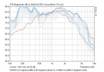
Hobby1: now I get it, in short no I don't observe the +6dB. But the graphs in post #2 and #8 are to a different SPL scale, SPL per V, than all the rest, which are in SPL per 2.83V. So I re-drew these earlier graphs. Below is the first, as of your request . SS8543 on ordinary 24x48x7 U-baffle, no muffler, 0-90 degrees (blue) and for comparison, the 0 degree line of the same driver on muffler with no baffle. No 6 dB reinforcement, to the contrary the peak around 1600-1800 Hz is attenuated when muffler is used rather than the large U-baffle. This is well in the driver's directional region though so we have a mixture of effects here.
John: the tweeter will be the XT1086 horn, with a height of 8.5" it's not easy to integrate. This fist batch of measurements was mainly to determine whether one could obtain clean midrange controlled directivity. It wasn't optimized for measuring LF or time domain. As for the LF polars I did not want to clutter the previous plot with too many overlays. But below 630 Hz down to under 300, the rear lobe does expand to quasi-figure eight.
Hobby1: now I get it, in short no I don't observe the +6dB. But the graphs in post #2 and #8 are to a different SPL scale, SPL per V, than all the rest, which are in SPL per 2.83V. So I re-drew these earlier graphs. Below is the first, as of your request
. SS8543 on ordinary 24x48x7 U-baffle, no muffler, 0-90 degrees (blue) and for comparison, the 0 degree line of the same driver on muffler with no baffle. No 6 dB reinforcement, to the contrary the peak around 1600-1800 Hz is attenuated when muffler is used rather than the large U-baffle. This is well in the driver's directional region though so we have a mixture of effects here. John: the tweeter will be the XT1086 horn, with a height of 8.5" it's not easy to integrate. This fist batch of measurements was mainly to determine whether one could obtain clean midrange controlled directivity. It wasn't optimized for measuring LF or time domain. As for the LF polars I did not want to clutter the previous plot with too many overlays. But below 630 Hz down to under 300, the rear lobe does expand to quasi-figure eight.
Attachments
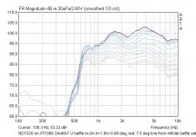
And for the record, the updated, standardized version of the 18Sound ND1020 on XT1086. The 7.5 degree line that had a glitch when measured on ordinary, 24x48x7" U-frame, was replaced with a line measured unrelatedly with setup on an infinite baffle (red), which also shows how little the baffle affects the FR here.
Edit: with 10uF protective cap acting as moderate HP.
Edit: with 10uF protective cap acting as moderate HP.
Attachments
hi
thank you for the information and your kindness!
I have mention this for the same reasons that John K,concerning implementation of the tweeter, it can give you ideas !!
y have to say that it's principaly the google traductor that is talking to you so ,excuse my very bad english....
thank you for the information and your kindness!
I have mention this for the same reasons that John K,concerning implementation of the tweeter, it can give you ideas !!
y have to say that it's principaly the google traductor that is talking to you so ,excuse my very bad english....
hobby1 said:hi
thank you for the information and your kindness!
I have mention this for the same reasons that John K,concerning implementation of the tweeter, it can give you ideas !!
Yes, Gradient has been doing the mid this way for some time. But also notice how they off center mount the mid to "smear" the diffraction over time.
- Status
- This old topic is closed. If you want to reopen this topic, contact a moderator using the "Report Post" button.
- Home
- Loudspeakers
- Multi-Way
- Adventures in cardioid