Hi,
I've been *slowly* putting together a couple of bookshelf speakers and was wondering if anyone could give me some advice regarding the physical construction of crossovers.
Due to the size of the caps and inductors I'm thinking its better to secure them on a more solid surface than a PCB and wire them up point to point. Is this the general way it is done?
Thanks in advance")
I've been *slowly* putting together a couple of bookshelf speakers and was wondering if anyone could give me some advice regarding the physical construction of crossovers.
Due to the size of the caps and inductors I'm thinking its better to secure them on a more solid surface than a PCB and wire them up point to point. Is this the general way it is done?
Thanks in advance
Would help to see how your schematic is done
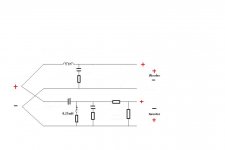
I always draw my schematic logically like this
And I find the best way to layout the components is exactly the way its done in schematic
On a piece of wood is fine
Use solidcore copperwire fore all "lines", mounted at the ends either through small wood "blocks" or solder terminals
I dont twist leads but just solder them together, very carefully
Fore mounting components I use polyurethane foam glue
If one driver(tweeter) needs to be reversed, I prefer to do it at output of filter, others do it at driver terminals
Attachments
crossover design
I just finished my first crossover, and I must say that I am very happy with my results.
The original xover was mounted on a piece of fibre board inside the speaker cabinet.
I built my replacement with high quality parts mounted on a 1 inch thick piece of oak plank. The parts were secured with a glue gun to the wood. I drilled holes into the wood and ancored the capacitors and resistor leads with hot glue and or epoxy into the wood. Then I wired it point to point with unshielded solid silver and copper wires. The crossover boards sit on the floor behind the speakers, and are wired to the drivers via separate solid wires. They sit on a sheet of bubble wrap to further insulate them from vibration.
I took an unconventional approach with the caps and used NOS BlackGate AC as opposed to the conventional wisdom of exotic film caps. 2 reasons. The BG AC had been listed in many posts as being as good as all but the best Mundorf Silver/Gold in Oil versions, and they are a fraction the price. Also the rest of my System is Black Gate equipped, and it just seemed kind of cool to have a tribute to the Black Gate legend. I used MILS resistors. The BG's do take a while to burn in. Right at first the improvement was dramatic. My system was already pretty well defined with a fully 3d sound stage and no apparrent speakers in the presentation. The new xover immediately moved mids and highs to clear and clean presentation. The last of symbols sounding more like polywrap being crunched was replaced by shimmering brass. I ran it for about 100 hours. It is now unbelievably opened up and cyristal clear. The sound stage is hudge and 3d airy. Voices are human and pianos are pianos. As I write this I'm listening to a guitar that is spooky real. Cello solo's are alive and vibrant.
I guess my message in all this is I listened to advice on the DIY forums and it worked for me. The advice was:
Put the xover outside the box.
Hard wire and solder everything. Strong physical connection / crimp first and a little solder to keep it that way.
Solid core wire everywhere in the signal path.
I like copper and pure silver. I use small guage 28awg for the high frequency and much larger copper for the lower registers.
Check out the capcitor shoot out pages and choose high value within your budget and expect them to take a while to reach their potential.
As with everything, keep vibration to a minimum.
Hope this helps.
Thanks everyone just the advice I needed I've actually headed down the path of a shielded enclosure which was surplus from work and figure because the crossover point is at a pretty common point for a two way (3kHz) I could use it to do preliminary testing on new designs.
Thanks again!
I've actually headed down the path of a shielded enclosure which was surplus from work and figure because the crossover point is at a pretty common point for a two way (3kHz) I could use it to do preliminary testing on new designs. Thanks again!
wiredmonkey said:
headed down the path of a shielded enclosure
Thanks again!
Iron is a big nono, but even aluminium affects the coils
Take a look here, and study very carefully, it is priceless information
http://www.troelsgravesen.dk/coils.htm
wiredmonkey said:Due to the size of the caps and inductors I'm thinking its better to secure them on a more solid surface than a PCB and wire them up point to point. Is this the general way it is done?
Indeed it's often done that way when using large air-core inductors, and it's my favourite approach. Although there are large sturdy PCB's designed for such components these are usually made to order and quite costly when purchased individually. They can be very useful for complex crossovers with a lot of components but most of the time it's easier to glue/strap components on a solid piece of wood and solder them point-to-point. Regarding inductor placement I highly recommend you refer to the link provided by Tinitus above, the method allows building reasonably compact layouts even with large inductors.
Some prefer using larger spacing but that often yields huge Xover boards that need to be placed outside the cabinet or in a specially built compartment that is not part of the enclosure volume. Usually such a compartment is built into the base of the cabinet under the bottom panel. Keep in mind that a large crossover can take up a fair amount of volume when placed inside a small enclosure, and sometimes it is not clear if the original designer included the Xover in volume calculations (if you are building a pre-designed system). When it's not mentioned I assume it's not included.
It's best to get all the inductors as far away from each other as possible. I just mount all the components on the back panel with Nylon Terminal strips http://www.allelectronics.com/make-a-store/item/TB-17/17.5-AMP-FEED-THROUGH-TERM-STRIP/-/1.html - just cut them up and screw them down.
A mechanical connection is much better than a soldered one anyways.
A mechanical connection is much better than a soldered one anyways.
gedlee said:It's best to get all the inductors as far away from each other as possible. I just mount all the components on the back panel with Nylon Terminal strips http://www.allelectronics.com/make-a-store/item/TB-17/17.5-AMP-FEED-THROUGH-TERM-STRIP/-/1.html - just cut them up and screw them down.
A mechanical connection is much better than a soldered one anyways.
This is a great idea! As a precaution though one should not mount the crossovers on the back panel until they are absolutely sure they're done working on it, obviously.
I hope you don't mind me posting a link to the document on your own site that explains this with a detailed picture (on page 4) of one of you're crossovers.
http://www.gedlee.com/downloads/Assembly Manual_noXo.pdf
- Status
- This old topic is closed. If you want to reopen this topic, contact a moderator using the "Report Post" button.
- Home
- Loudspeakers
- Multi-Way
- Crossover construction techniques