I've nearly finished my latest project and thought I'd put up a few pictures. I'll attach a few more of the build shortly.
Here are the basics.
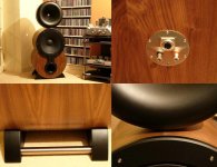
The two drive units are a Kappalite 3015 for the bass and a B&C DE-500 for the top end. The horn is conical with an aluminium adapter plate to mate the initial flare of the DE-500 to the 90 degree horn. It was the search for a drive unit that led me to this site and to the work of Earl Geddes. However, the horn was almost complete by the time I'd come across OS waveguides, and since it was time-consuming without a lathe, I'm in no hurry to do it again with an OS profile. But in light of what I've read here I'm interested to give it a go.
The bass cabinet is made from 4 layers of 6mm flexible MDF which, when fixed around the birch ply frame, gives a very rigid structure. The cabinet is lined with a heavy duty polymer damping sheet which seems to be a nice improvement on the bitumen pads. On top of this is a compressed wool felt, and directly around the driver is an additional layer of acoustic egg-shell type foam.
I wanted a kind of musical instrument look, hence the cabinet shape and the stainless steel frets on the front. There is still a few things to finalise, like the crossover (which is nearly done) and how to get the connection from the horn to the main cabinet to look tidy, but hopefully the next couple of weeks should see this all sorted. I built a rectangular test box prior to doing the real thing and like what heard, although there did seem to be a slight brightness to the sound despite a very flat response.
Steve
Here are the basics.
The two drive units are a Kappalite 3015 for the bass and a B&C DE-500 for the top end. The horn is conical with an aluminium adapter plate to mate the initial flare of the DE-500 to the 90 degree horn. It was the search for a drive unit that led me to this site and to the work of Earl Geddes. However, the horn was almost complete by the time I'd come across OS waveguides, and since it was time-consuming without a lathe, I'm in no hurry to do it again with an OS profile. But in light of what I've read here I'm interested to give it a go.
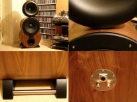
The bass cabinet is made from 4 layers of 6mm flexible MDF which, when fixed around the birch ply frame, gives a very rigid structure. The cabinet is lined with a heavy duty polymer damping sheet which seems to be a nice improvement on the bitumen pads. On top of this is a compressed wool felt, and directly around the driver is an additional layer of acoustic egg-shell type foam.
I wanted a kind of musical instrument look, hence the cabinet shape and the stainless steel frets on the front. There is still a few things to finalise, like the crossover (which is nearly done) and how to get the connection from the horn to the main cabinet to look tidy, but hopefully the next couple of weeks should see this all sorted. I built a rectangular test box prior to doing the real thing and like what heard, although there did seem to be a slight brightness to the sound despite a very flat response.
Steve
Attachments


If you look at the pictures, you will see that the MDF is kerfed.domtw said:Very nice looking and finishing !
What is "flexible MDF" is it a special kind of MDF or it is flexible because of its small thickness ?
domtw,
The rings that make up the horn were done using a router mounted on a radial arm saw. I bolted a 25mm bearing to the saw table and put a 25mm hole in each of the plywood discs. Each disc was then rotated on the bearing and the router used to trim the outside to get a perfect circle - that was the easy part.
Having calculated the inside diameter required where each disc would join the next (simple spreadsheet), I used a 45 degree V-groove bit to remove the centre section. The disc was rotated by hand while the router was plunged until I got to the very last ply. You can't cut all the way through because the centre section is holding the disc on the bearing, but the plywood makes it easy because you can count the ply as you go. Once removed from the bearing a sharp knife can be used to free the centre section. It is quite time consuming, but very careful measurement and fine adjustment of the router to obtain the correct diameter will leave you with a number of rings that mate together with very little finishing required. The rings were then glued and screwed, mounted onto a simple spindle and a sanding flap wheel used to finish the surface.
Steve
- Status
- This old topic is closed. If you want to reopen this topic, contact a moderator using the "Report Post" button.
- Home
- Loudspeakers
- Multi-Way
- Waveguide and curved cabinet finished