Most of you are familiar with the Dayton Reference series aluminum cone speaker, and you are also familiar with the fact that they uniformly all have a nasty break up and peak in the high frequencies.
So, I had this idea of starting at my selected frequency with a standard 12 db/oct crossover, then just before I reach the break up region kicking in an additional -6db/oct crossover.
Using the 8" Dayton Reference woofer as an example -
http://www.parts-express.com/pdf/295-366s.pdf
So, I would start out, as an illustration, with a 800hz low/mid crossover of -12db/oct. Then around 3khz I would add in another -6db/oct component to tame the break up region.
It was just a thought, but I'm unclear as to what the complication would be, or how to determine the values of the components.
Is this a waste of time? Would I just be better off using a straight forward 3rd order crossover?
In my mind, conceptually, the thought of a cascading crossover seems like a good idea. But again, do I just follow a 2nd order with a 1st order? Do I use the values for a 3rd order at 800hz but change the second capacitor to the value necessary for a 3khz crossover?
At this point, this is all theoretical. I'm wondering if the concept has ever been tried before, and I'm wondering what design considerations I would need to keep in mind if I ever decided to do this?
Too much time and not enough money on my hands.
Steve/bluewizard
Years ago I heard through the rumor mill that at least some of the Apogee speakers used a relatively shallow roll-off at the crossover point, and then added further attenuation an octave or two away from that point. I have not verified that, though, so perhaps someone with more direct experience with those speakers can speak with more authority.
Few
Few
BlueWizard said:
So, I would start out, as an illustration, with a 800hz low/mid crossover of -12db/oct. Then around 3khz I would add in another -6db/oct component to tame the break up region.
It was just a thought, but I'm unclear as to what the complication would be, or how to determine the values of the components.
Is this a waste of time? Would I just be better off using a straight forward 3rd order crossover?
Steve/bluewizard
You'd be better off using a "single" crossover of higher order. A crossover's characteristics are not just about cutoff and slope. The "alignment" of the crossover - its ripple/transient characteristics - must also be considered. For example, cascading two Butterworth filters (which have a certain set of characteristics) at the same frequency gives you a LR characteristic (which is different). If the frequencies are spread out really far apart (and 800 and 3k are not far enough) then the sections may be treated as independent. Otherwise the resulting alignment will not have the same characteristics or alignment as the original one, which means that in your case even at frequencies below 800Hz you do not have the same characteristic of the 12 dB section acting alone.
HTH
-Ram
www.audesine.com
I believe part of Apogee's motivation was precisely to take advantage of the better transient response associated with shallow filters while still providing adequate attenuation of frequencies well into the stop band. Clearly you don't end up with any of the "classical" responses (Butterworth, Bessel, ...) this way but it wouldn't be the first time a non-textbook approach worked well.
I'm really dredging my memory here, but my recollection of an interview with Jason Bloom--Mr. Apogee--was that he claimed this approach is used in non-audio applications (for some reason microwave frequencies come to mind but I could be way way off on that) and he was surprised it wasn't more widely used in audio.
In any case, I don't mean to champion this approach. I'm just contributing my recollections in case they help Steve track down more information.
Few
There is no reason not to do this if it helps. The bottom line with any crossover is what makes it work. The idea that an ideal electrical crossover will be ideal on the acoustic responses of a set of drivers is ridiculous. So if cascading filters makes it work, then do it. I do this all the time. But just remeber that its the final Acoustic response that matters not the electrical response.
However, from a given number of components, you will get more HF rejection from a properly designed third order filter than you will with a cascaded set as you have described. But if it works then do it.
However, from a given number of components, you will get more HF rejection from a properly designed third order filter than you will with a cascaded set as you have described. But if it works then do it.
Thank for the replies.
In pure concept, this seemed like a good idea. The one part of it the left me feeling uneasy though was, how do I make sure the filters stay separate and not merge together into a single filter that doesn't conform to either selected crossover point.
As ramkumarr implies, you can't. The capacitance will indeed merge together in a bad way.
In a sense, what I envisioned looked exactly like a standard 18db/octave crossover. It is a T-filter, using the HF as an example, it has a series cap, followed parallel coil, followed by another series cap. Though separated by the coil, we have two caps in series.
Does the coil isolate them so they don't interact? It must to some extent to get a standard 3rd order crossover to work. But I also notice that, in a standard 3rd order, the second cap doesn't match the first. One would assume that you simply cascade three identical stages together to get a 3rd order. But that is clearly not true. Something is effecting the second cap to require a value change.
So, while I still like the idea, I don't see anyway to figure it out logically. So, I'm stuck with cut-n-try, which doesn't seem very scientific, nor very cost effective.
Still despite all my rambling, I do appreciate the responses.
Steve/bluewizard
This is something of a dead subject, but I must admit, conceptually, I still like the idea of a two-stage cascading crossover.
I'm sure I'm creating many more problems than I think I'm solving but what if the standard lower frequency 12db/oct was in the high side, and the higher frequency 6db/oct was in the low side?
Would the speaker impedance isolate the two and keep them separate? Or, in the far more likely case, am I just delusional?
Steve/bluewizard
Member
Joined 2009
Music and Design - Duelund_and_Beyond
I was just looking at this. It might be of interest.
-----------
I'm not an expert but I think a well placed notch filter will work best in your case.
I was just looking at this. It might be of interest.
-----------
I'm not an expert but I think a well placed notch filter will work best in your case.
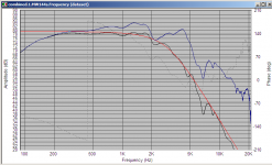
That daytons breakup is very nasty! I was going to suggest using a notch filter, but after seeing that curve I'm not so sure. you might need two tuned a bit to each side of the peak, as getting something broad enough would be difficult.
attached is a plot comparing original vs with notch filters and a some what standard 2nd order filter.
Tony.
attached is a plot comparing original vs with notch filters and a some what standard 2nd order filter.
Tony.
Attachments
Hi Blue Wizard.
I have thought along these lines for a while. A good idea and easy to implement.
I think it is useful to start with an appropriate Zobel across the driver. Then insert your first order compensation. Next another Zobel (or "conjugate matching network"....all the rage with Kef 25yrs ago.) That gives you the right termination for the second order cross over....
It sound complicated but its not too bad and the zobels are not expensive as you are only buying a couple of caps and resistors. If the original graphs for the driver are right you can pretty much use standard values from the usual tables for xover/frequency...
Go for it.
Jonathan
Keep in mind, my idea was a 12db/oct at 800hz cascaded with an additional 6db/oct at 4khz. So, 12db between 800hz and 4khz, then 18db from 4khz upward.
But it is the details of how to do this that allude me.
Though the idea of a notch filter in the offending range probably makes the most sense.
But, I'm still somewhat worried about the two filters interfering with each other in some undesirable way.
But likely either starting with a 18db filter or using a 12db with a notch in the offending area are probably wiser choices.
Again, this is all hypothetical. I was just intrigued by the idea of a two-stage filter on a given speaker, and couldn't work out how that could be done, as least not with passive filters. Active, I speculate, would be no problem.
Again, just curious.
Steve/bluewizard
The location of the break-up is at 4 kHz, which is 5 octaves above f3 (800 Hz) of your 12 dB/ octave low-pass filter. So that means that in theory your 12 dB/ octave filter has reduced the level of the driver by 60 dB at 4 kHz. Assuming that roll-off by the 12 dB/ octave filter is close to theoretical and that it is the only filter connected to the driver, wouldn't that result in break-up of the driver being mostly inaudible?
Sorry if I'm showing lack of experience. I have to say that I haven't ever actually tried to compensate for break-up of a driver.
Regards,
Pete
Sorry if I'm showing lack of experience. I have to say that I haven't ever actually tried to compensate for break-up of a driver.
Regards,
Pete
I just picked those crossover numbers at random to illustrate the point.
If a person wants to be more realistic, you could pick 2.5khz and 4khz.
I'm going from memory here, but I think in the break-up region of some metal cone drivers, the output level is higher than it is in the normal working range. So, the break up is pretty significant.
You are right about my 800/4k example though. That is one of the way to deal with the break-up. Crossover low enough that the circuit is massively attenuated in the break-up region.
Again, this is all theoretical. I was just intrigued by the concept of a cascading crossover.
Steve/bluewizard
Break-ups are easily tamed with an active digital crossover and I would suggest using a PEQ or Notch filter at the nasty break-up frequency / area.
Try it out for yourself on the unfiltered Alu midrange in this example:
http://www.groundsound.dk/DiyAudio/Mivoice 3_DiyAudio.xow
Hint #1: Double click the EQ box and enable the filters.")
Download the digital crossover software tool for the example.
Hint #2: You can import measurements of your own driver in the Driver box.
Hint #3: Double click Band Response window for a larger view.
Regards, Robert GS
Try it out for yourself on the unfiltered Alu midrange in this example:
http://www.groundsound.dk/DiyAudio/Mivoice 3_DiyAudio.xow
Hint #1: Double click the EQ box and enable the filters.
Download the digital crossover software tool for the example.
Hint #2: You can import measurements of your own driver in the Driver box.
Hint #3: Double click Band Response window for a larger view.
Regards, Robert GS
Filters are cascaded as a matter of course to get the desired final response. For a sharp resonant peak use a gyrator shunt to bring it down.
It's not 5 octaves, but 2.3.The location of the break-up is at 4 kHz, which is 5 octaves above f3 (800 Hz)
Last edited:
Assuming that roll-off by the 12 dB/ octave filter is close to theoretical and that it is the only filter connected to the driver, wouldn't that result in break-up of the driver being mostly inaudible?
The only problem I can think of (sorry if this has been covered, but I'm just randomly commenting on things) is even if you cross a driver over so that it's breakup peak is down an appropriate amount of DB, the problem you still might have are harmonics exciting the resonance from frequencies that the driver is still playing.
If a driver has a nasty breakup peak, you have to make sure that, even if it's outside of the crossover range, you aren't still exciting the driver at those frequencies with lower frequencies that have higher order harmonics at the breakup points, if that makes any sense.
It might be my 530am tired response, but that makes no sense. How is a 4k signal of a given level any different if it is generated as original source material, or a distortion component? Same level, same filtering, same response from the system. Harmonic compnents are always lower than the fundamental except in some very weird circumstances.The only problem I can think of (sorry if this has been covered, but I'm just randomly commenting on things) is even if you cross a driver over so that it's breakup peak is down an appropriate amount of DB, the problem you still might have are harmonics exciting the resonance from frequencies that the driver is still playing.
If a driver has a nasty breakup peak, you have to make sure that, even if it's outside of the crossover range, you aren't still exciting the driver at those frequencies with lower frequencies that have higher order harmonics at the breakup points, if that makes any sense.
It might be my 530am tired response, but that makes no sense. How is a 4k signal of a given level any different if it is generated as original source material, or a distortion component? Same level, same filtering, same response from the system. Harmonic compnents are always lower than the fundamental except in some very weird circumstances.
The idea is that you can cross a driver over electrically so that the fundamental frequency doesn't excite the resonance, but in operation, you can play frequencies that are in the operational range of the driver, but their distortion harmonics ring in the driver acoustically, regardless of the crossover frequency.
Let's say a driver has a cone breakup resonance at 3.6 khz. If you cross this driver over at 2khz and then play a 1.8 khz tone, the first harmonic is going to be at 3.6 khz, which will ring the cone at it's breakup frequency, unless I've made a grave error in my research of resonances.
To answer your question directly, distortion components are generated by the driver itself and aren't subjected to the filter characteristics of the crossover.
http://www.csgnetwork.com/harmonicscalc.html
Last edited:
- Status
- This old topic is closed. If you want to reopen this topic, contact a moderator using the "Report Post" button.
- Home
- Loudspeakers
- Multi-Way
- Cascading Crossovers - Just a Thought.