Hello revintage,
Because we are less sensitive to phase distorsion at low frequency, the rule to use an electrical cut-off frequency for the high pass crossover one octave above the acoustical cut-off of the horn can be overpassed.
So you can use a lower cut off than 400Hz for a 200Hz horn .
Best regards rom Paris, France
Jean-Michel Le Cléac'h
Could we suppose that the cutoff-frequency, in ballpark figures, can be twice the design-frequency?
Hello,
In his white paper about directivity
http://www.gedlee.com/downloads/directivity.pdf
(A white paper by Dr. Earl Geddes, GedLee LLC )
Earl Geddes defines on page 9 what is the "optimum" frequency response curves (shown at 0°, 15°, 30° 45° and 60°) for a sterophonic listening in order that the frequency response remain constant in a "listener plane" (3 listening positions called A, B and C are shown in that plane)
The optimum frequency curves as defined by Earl Geddes are shown on figure 11 of the document.
Also on figure 10 an achievable "optimum" polar map is shown (showing that a slightly increasing directivty with frequency is desireable).
From the measurements made by Jack Zagaja on the E-JMLC-1000 horn I could retrieve the frequency curves at 15°, 30° 45° and 60° after the 0° response is flatten.
You can see on the attached graph, the comparison between the frequency response curves obtained on the E-JMLC-1000 horn and the "optimum" frequency response curves defined by Earl Geddes.
The fit is very good specially between 2.5kHz and 7kHz.
The EOS waveguide, due to the (3dB) hole between 3kHz and 6kHz
http://2.bp.blogspot.com/_vk3bkhlDpPg/TReaDrjXfmI/AAAAAAAAASI/LSersg1OW6Y/s1600/summa_FR.jpg
doesn't reach that result.
Can we conclude that the E-JMLC horn meet both the requirements of the best horns in matter of loading and smoothness of the response curves an an excellent directivity control as the best waveguides?
Best regards from Paris, France
Jean-Michel Le Cléac'h
Attachments
To what extent?
Specific conditions for a compression driver, assuming displacement limit, [Fs] and horn length are not at issue:
[n] Octave above ([F3] = [n]*2*[Fc]): 1 3/4 1/2 1/4
...................................HP filter slope:.?...?.....?.....?
Regards,
WHG
Hello revintage,
Because we are less sensitive to phase distorsion at low frequency, the rule to use an electrical cut-off frequency for the high pass crossover one octave above the acoustical cut-off of the horn can be overpassed.
So you can use a lower cut off than 400Hz for a 200Hz horn .
Best regards rom Paris, France
Jean-Michel Le Cléac'h
Specific conditions for a compression driver, assuming displacement limit, [Fs] and horn length are not at issue:
[n] Octave above ([F3] = [n]*2*[Fc]): 1 3/4 1/2 1/4
...................................HP filter slope:.?...?.....?.....?
Regards,
WHG
Last edited:
I've read another paper that has a different point of view as calculated based in Interaural Time difference and Interaural Intensity Difference. So I wonder how the referenced paper here defines the ideal directivity.Hello,
In his white paper about directivity
http://www.gedlee.com/downloads/directivity.pdf
(A white paper by Dr. Earl Geddes, GedLee LLC )
Earl Geddes defines on page 9 what is the "optimum" frequency response curves (shown at 0°, 15°, 30° 45° and 60°) for a sterophonic listening in order that the frequency response remain constant in a "listener plane" (3 listening positions called A, B and C are shown in that plane)
The optimum frequency curves as defined by Earl Geddes are shown on figure 11 of the document.
Also on figure 10 an achievable "optimum" polar map is shown (showing that a slightly increasing directivty with frequency is desireable).
From the measurements made by Jack Zagaja on the E-JMLC-1000 horn I could retrieve the frequency curves at 15°, 30° 45° and 60° after the 0° response is flatten.
You can see on the attached graph, the comparison between the frequency response curves obtained on the E-JMLC-1000 horn and the "optimum" frequency response curves defined by Earl Geddes.
The fit is very good specially between 2.5kHz and 7kHz.
The EOS waveguide, due to the (3dB) hole between 3kHz and 6kHz
http://2.bp.blogspot.com/_vk3bkhlDpPg/TReaDrjXfmI/AAAAAAAAASI/LSersg1OW6Y/s1600/summa_FR.jpg
doesn't reach that result.
Can we conclude that the E-JMLC horn meet both the requirements of the best horns in matter of loading and smoothness of the response curves an an excellent directivity control as the best waveguides?
Best regards from Paris, France
Jean-Michel Le Cléac'h
Hello WH Heiger,
I consider the user of my recommandation sufficiently clever as to do the best choice in order that the phase distortion of the whole group delay curve will be sufficiently unaffected by the rise of the group delay of the horn near its acoustic cut-off.
But a 3rd order Butterworth high-pass filter the f-3dB of which is set one octave above Fc will do the job.
Best regards from Paris, France
Jean-Michel Le Cléac'h
Specific conditions for a compression driver, assuming displacement limit, [Fs] and horn length are not at issue:
[n] Octave above ([F3] = [n]*2*[Fc]): 1 3/4 1/2 1/4
...................................HP filter slope:.?...?.....?.....?
Regards,
WHG
FWIW
JMLC,
The question I asked was for the benefit of other readers, myself included.
For the example cited, [n]=1 & [m]=18 db/Oct, there is no "overpass".
Typically, [n]=3/4, [m]=12 dB/Oct is the lower bound.
Is this later example what you mean by "overpass"
What is the experience with your horns regarding the setting of min[F3]?
Regards,
WHG
Hello
Jack Zagaja used to show the directity sonogram of the E-JMLC-1000
http://www.diyaudio.com/forums/atta...cleach-horns-e-jmlc-1000_bms4538_sonogram.gif
It is interesting to compare that result to the directivity sonograms published on that site:
Red Spade Audio: Waveguide shootout
Best regards from Paris, France
Jean-Michel Le Cléac'h
http://www.diyaudio.com/forums/atta...cleach-horns-e-jmlc-1000_bms4538_sonogram.gif
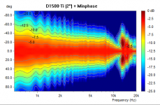
Article shows directivity sonograms normalized to 0 deg where there will be always narrowing of directivity because of WG resonances and mouth diffraction. Better normalize to arbitrary angle or power response. Otherwise non axi-symmetrical WGs will always "look" better. Michael's Minphase horn seems the smoothest.
Attachments
Last edited:
Hype!
The following closing remarks clearly demonstarte the mission of this "white paper":
"Basically no loudspeaker which does not use a waveguide is going to be able to match the Summas performance. Piston source loudspeakers simply cannot do what a waveguide does. But all waveguides are not equal either. The Summa has a particularly high directivity, which is desirable in a small room (another topic altogether)."
Regards,
WHG
I've read another paper that has a different point of view as calculated based in Interaural Time difference and Interaural Intensity Difference. So I wonder how the referenced paper here defines the ideal directivity.
The following closing remarks clearly demonstarte the mission of this "white paper":
"Basically no loudspeaker which does not use a waveguide is going to be able to match the Summas performance. Piston source loudspeakers simply cannot do what a waveguide does. But all waveguides are not equal either. The Summa has a particularly high directivity, which is desirable in a small room (another topic altogether)."
Regards,
WHG
True, but the AES publication I read also agrees with controlled directivity. However, it was shown that dispersion profile and speaker location, toe-in etc. are interrelated. Additionally, if I recall correctly, a bit more beeming is required at the low frequency. This also possibly explains why people find large woofers have better bass performance than small long throw woofers.
Size Matters
Once signal wave-length becomes comparable to driver or horn dimensions, there is no pattern control. Larger [Sd] will yield a lesser impedance mismatch between the driver and surrounding air, until again, signal wave length becomes much greater then driver circumference. Here only a room corner (horn) will confine LF pattern. At VLF it is a pressure response in the listening space that becomes dominate. So horn, no horn issues are irrelevant, it is a matter of brute force [Vd] only. Here the larger the [Sd] the better, assuming constant [xmax].
True, but the AES publication I read also agrees with controlled directivity. However, it was shown that dispersion profile and speaker location, toe-in etc. are interrelated. Additionally, if I recall correctly, a bit more beeming is required at the low frequency. This also possibly explains why people find large woofers have better bass performance than small long throw woofers.
Once signal wave-length becomes comparable to driver or horn dimensions, there is no pattern control. Larger [Sd] will yield a lesser impedance mismatch between the driver and surrounding air, until again, signal wave length becomes much greater then driver circumference. Here only a room corner (horn) will confine LF pattern. At VLF it is a pressure response in the listening space that becomes dominate. So horn, no horn issues are irrelevant, it is a matter of brute force [Vd] only. Here the larger the [Sd] the better, assuming constant [xmax].
I tend to feel that normalizing to 0 deg is more usefull.Article shows directivity sonograms normalized to 0 deg where there will be always narrowing of directivity because of WG resonances and mouth diffraction. Better normalize to arbitrary angle or power response. Otherwise non axi-symmetrical WGs will always "look" better. Michael's Minphase horn seems the smoothest.
At least according to some simulations I have done, it seems there might be some hope of extending pattern control with the horn. How to apply it in real application becomes a bit tricky. I am still trying to figure out what criteria should be applied.Once signal wave-length becomes comparable to driver or horn dimensions, there is no pattern control. Larger [Sd] will yield a lesser impedance mismatch between the driver and surrounding air, until again, signal wave length becomes much greater then driver circumference. Here only a room corner (horn) will confine LF pattern. At VLF it is a pressure response in the listening space that becomes dominate. So horn, no horn issues are irrelevant, it is a matter of brute force [Vd] only. Here the larger the [Sd] the better, assuming constant [xmax].
Since pressure and velocity pattern influence how reflections occur, and thus also effect the perception due to timing and reflection pattern.
As shown below, different patterns seem to effect the room modes.
An externally hosted image should be here but it was not working when we last tested it.
An externally hosted image should be here but it was not working when we last tested it.
An externally hosted image should be here but it was not working when we last tested it.
I tend to feel that normalizing to 0 deg is more usefull.
I think it is the most logical to normalize to the listening axis (0° for a conventional setup, or for example 22° for extreme toe-in like recommended for the geddes speakers), this because you would want the direct sound to be reasonably flat, and you want to see how "bad" the off axis response will be if you use this kind of horn/waveguide in your setup.
Compact MB Horn
Have a look at this:
10" mid bass horn - Speakerplans.com Forums - Page 1
Regards,
WHG
200 would be fine for me i'm a little bit short in space")
Have a look at this:
10" mid bass horn - Speakerplans.com Forums - Page 1
Regards,
WHG
- Home
- Loudspeakers
- Multi-Way
- Jean Michel on LeCleac'h horns