Hello Angelo,
You asked a lot of questions and I prefer to reply one after the other.
The large horn system on homepage of the Melaudia association :
http://www.melaudia.net/zimage/pavFD-533x400.jpg doesn't belong to me but to a friend. I still have not listened to this horn but shall during the weekend of March 28th and 29th because Melaudia organize a public demonstration of that system (well the bass reflex will be different, the Onken W enclosure will be used).
Best regards from Paris, France
Jean-Michel Le Cléac'h
angeloitacare said:does it make sense to use such a big horn as the last pictures shown of melaudia homepage, with the Radian 950pb, if its Fs is 500hz ? have you heard this system ?
Jean-Michel,Jmmlc said:Hello sqlkev,
That's probably due to the thrill in my spine when I listen to such good drivers as Onken, Goto, Western Electric... I never experienced such with cone drivers mounted on horns, even if some of them were very good sounding compared to 90% of the commercial stuff
The resonance frequency (mounted on the horn it may differ than the one mesured on planar wave tube) plays a role for sure in the sound. Generally I try to avoid the resonance frequency to be in the middle of the useful bandwith of the horn
The Goto and the WE possess low resonance frequency, may be that's one of the reasons why I liked them so much.
Best regards from Paris, France
Jean-Michel Le Cléac'h
I guess i've been looking at the wrong places when it comes to compression drivers then.
")
Those highend drivers you've mentioned are out of reach for me, so i'll have to go with cone drivers for the lowend instead.
How do you feel about loading a dome midrange for a midrange unit? The fs should be around 400hz right where i want it.
do i model it the same as a compression unit using the measured T/S from a regular baffle?
thanks again for your contribution
Kev
Hello sqlkev,
Low mid compression drivers are rare and expensive at the moment.
Most 2inches compression drivers from JBL, TAD, etc... don't give good results when loaded by a low-mid horn. If you want to use a compression driver that you can use in the low-mid (at the exepense of a lowered max power), you have to choose one with the diaphragm using a non metallic suspension (with the exception of exotic suspension as in the JA6681B). Friends of mine obtained good results with Radian compression drivers (or even with JBL 2inches drivers and a Radian diaphragm).
If you want to initiate yourself to low-mid compression drivers on horns there is a very cheap solution (but the results are surprisingly good for the price!), try this:
http://www.skytronic.co.uk/product/index.php?s=952.207
I am not very familiar with dome midrange even if 15 years ago I used to play with a Dynaudio loudspeaker which was excellent.
If you limit its use to above 1kHz this loudspeaker recommanded by Helmuth seems promising (very good waterfall).
http://www.diyaudio.com/forums/showthread.php?postid=1774395#post1774395
Yes you can use T&S parameters of your loudspeaker to simulate the horn (in Hornresp, Akabak, J Horn...) .
Best regards from Paris, France
Jean-Michel Le Cléac'h
sqlkev said:
Jean-Michel,
I guess i've been looking at the wrong places when it comes to compression drivers then.
Those highend drivers you've mentioned are out of reach for me, so i'll have to go with cone drivers for the lowend instead.
How do you feel about loading a dome midrange for a midrange unit? The fs should be around 400hz right where i want it.
do i model it the same as a compression unit using the measured T/S from a regular baffle?
thanks again for your contribution
Kev
Useful links
A few posts back, you were talking about the power factor or reactivity/resistance ratio of horns. We had a lot of discussions about that on AudioRoundTable.com a few years back, mostly about how it appeared in truncated horns like basshorns but also how it appeared in every horn to a greater or lesser extent, depending on acoustic size, flare features and boundary conditions.
In the post below, there are a couple dozen links to references around the internet with very useful information, which I think you'll find germane to this discussion and also to acoustic waveguide discussions. Pipe mode and Helmholtz resonance, directivity, evanescent modes and wavefront propogation are referenced there.
Jmmlc said:... a very cheap solution (but the results are surprisingly good for the price!), try this:http://www.skytronic.co.uk/product/index.php?s=952.207
Funny! I often see these type of drivers in US catalogs, usually with a 70V transformer. None of them are as pretty as the Skytronic, tho.
Have always wondered how they sound.Re: Useful links
Hello Wayne,
Thanks for the pointed list of links, it is interesting to have such compilations.
I used to read few disscussions on your website but not that one.
Bass horns are good examples to illustrate the "tuned pipe" effect of truncated horns. I am aware of that and that's why I recommand bass horns as in the attached file.
These are few examples:
http://img383.imageshack.us/my.php?image=dsc30511280x768ac0.jpg
http://www.diyaudio.com/forums/attachment.php?s=&postid=1770740&stamp=1236807427
(The best bass I could listen to was delivered by that "Le Cleac'h" bass horn built by my friend Frédéric Lebas)
Those 2 examples will still show some diffraction due to the upper edge of the mouth but that one
http://ndaviden.club.fr/pavillon/exemples/front.jpg
will have less due to its height quasi equal to the height of the room.
One advantage of using the total width of a room for building such horns is that the quasi cylindrical wavefronts can develop gently very far from the throat (see attached graph). The amount of reflected energy as I could see on pulse measurement of the second horn is low.
Best regards from Paris, France
Jean-Michel Le Cléac'h
Wayne Parham said:A few posts back, you were talking about the power factor or reactivity/resistance ratio of horns. We had a lot of discussions about that on AudioRoundTable.com a few years back, mostly about how it appeared in truncated horns like basshorns but also how it appeared in every horn to a greater or lesser extent, depending on acoustic size, flare features and boundary conditions.
In the post below, there are a couple dozen links to references around the internet with very useful information, which I think you'll find germane to this discussion and also to acoustic waveguide discussions. Pipe mode and Helmholtz resonance, directivity, evanescent modes and wavefront propogation are referenced there.
Attachments
Speaking of impedance in horns, here is a graph just for fun. My measurement of the same 1" compression driver with 3 different loads.
Magenta line is the driver unloaded (no horn)
Green line is a homemade roound Tractrix horn. Mouth diameter ~10"
Blue line is the same driver on an Altec 811b horn. Note the midband ripple.
I couldn't seem to find it, but I did have a measurement of the 811 horn with a roll-over added to the mouth. It was smoother.
Attachments
I did not mention before to scan through the other posts in the thread on ART for more links, but do. In particular, see the ones about the Acoustical Klein-Gordon Equation, Benade's papers on musical instrument acoustics and the original "Basshorn or Transmission Line" post that compares a basshorn with a tuned pipe. It shows (resistive/reactive) impedance and amplitude response using a Hornresp simulation of a typical basshorn.
Re: Re: Useful links
This configuration looks particularly interesting. The spreadsheet would probably need modification to do this calculation.Jmmlc said:.
...
http://ndaviden.club.fr/pavillon/exemples/front.jpg
will have less due to its height quasi equal to the height of the room.
...
Best regards from Paris, France
Jean-Michel Le Cléac'h
After many tries, this is about the best I can get. It does seem that a more conventional baffle edge diffraction control scemes would be more promissing though.soongsc said:
Jean-Michel, Thanks for pointing this out. Looking at the dimensions, I was wondering the same thing. I just need to figure out how to do it with this software. Right now it seems like extending the horn so that the baffle is far away from the lip is the only alternative, so I may just put the horn 1 meter in front of the baffle.
Attachments
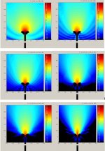
Here is a comparison among the various positions involving lip shape.
As expected, it seems that out in the open will widen up the beam. Also, it seems that the small radius lip really creates ripples in the response, which is quite expected in terms of edge diffraction. The actual wave guide built just brought the sides staight back tangent to the lip. So it would be interesting what measurements would look like.
An externally hosted image should be here but it was not working when we last tested it.
As expected, it seems that out in the open will widen up the beam. Also, it seems that the small radius lip really creates ripples in the response, which is quite expected in terms of edge diffraction. The actual wave guide built just brought the sides staight back tangent to the lip. So it would be interesting what measurements would look like.
Jmmlc said:Hello sqlkev,
Low mid compression drivers are rare and expensive at the moment.
Most 2inches compression drivers from JBL, TAD, etc... don't give good results when loaded by a low-mid horn. If you want to use a compression driver that you can use in the low-mid (at the exepense of a lowered max power), you have to choose one with the diaphragm using a non metallic suspension (with the exception of exotic suspension as in the JA6681B). Friends of mine obtained good results with Radian compression drivers (or even with JBL 2inches drivers and a Radian diaphragm).
If you want to initiate yourself to low-mid compression drivers on horns there is a very cheap solution (but the results are surprisingly good for the price!), try this:
http://www.skytronic.co.uk/product/index.php?s=952.207
I am not very familiar with dome midrange even if 15 years ago I used to play with a Dynaudio loudspeaker which was excellent.
If you limit its use to above 1kHz this loudspeaker recommanded by Helmuth seems promising (very good waterfall).
http://www.diyaudio.com/forums/showthread.php?postid=1774395#post1774395
Yes you can use T&S parameters of your loudspeaker to simulate the horn (in Hornresp, Akabak, J Horn...) .
Best regards from Paris, France
Jean-Michel Le Cléac'h
excellent info!
i'll look into ordering a set of those low-mid skytronic compression drivers
do you happen to know the throat diameter on the 952.207 driver?
952.210
Power rms 40W
SPL @ 1W/1m 112.5dB
Dimensions 125 x 125mmØ 1
Weight 2.0kg
Packed Gift Box
Would you know anything about this particular model?
952.210
Power rms 60W
SPL @ 1W/1m 113.5dB
Dimensions 172 x 150mmØ
Weight 2.5kg
Packed Gift Box
I'm from the US and i can't find any dealers around here, anyone with leads to a reputable place where i can order these?
soongsc,
what were the components you used in modeling those?
a perfect compression driver in a tweeter lecleach horn? any specs of the horn?
Hello Soogsc,
As long as you'll not solve the problem of the reflective boundary (lower horizontal edge in your graphs) it will be difficult to separate the artefacts due to reflection on that hard boundary from diffraction at the mouth.
About the baffling what I think is that it will be harmless only if it is infinite. Finite baffling of horns or waveguide is IMHO a twisted solution. (When I see waveguides with 1 or 2 inches baffling I smile...). How large is the baffle do you plan to use?
If you know that width, then you'll have to simulate the finite width baffled waveguide in the same conditions as the one with rolled back lips that means separate from 1 meter of the lower horizontal reflective boundary.
(Most probably the software you use may accept that you change the property of the limits of the area simulated. Please, check.)
Best regards from Paris, France
Jean-Michel Le Cléac'h
soongsc said:Here is a comparison among the various positions involving lip shape.
As expected, it seems that out in the open will widen up the beam. Also, it seems that the small radius lip really creates ripples in the response, which is quite expected in terms of edge diffraction. The actual wave guide built just brought the sides staight back tangent to the lip. So it would be interesting what measurements would look like.
Hello sqlkev,
I only know the 60 watt model. With a friend, we used to try it on large ROUND Vitavox HE190 horns that accept that driver.
What is sure is that you cannot use that driver inside a large badnwith. But if you lilmit its use to the range 200Hz to 1200Hz it is very good on voices.
I was informed that Monacor sells the same driver under reference KU-516
http://www.monacor.de/typo3/kataloge/ELA_2009_FR/
The throat is 1inch3/8 ( = 3,5cm)
Best regards from Paris, France
Jean-Michel Le Cléac'h
sqlkev said:
excellent info!
i'll look into ordering a set of those low-mid skytronic compression drivers
do you happen to know the throat diameter on the 952.207 driver?
Would you know anything about this particular model?
952.210
Power rms 60W
Hello Jean-Michel,Jmmlc said:Hello Soogsc,
As long as you'll not solve the problem of the reflective boundary (lower horizontal edge in your graphs) it will be difficult to separate the artefacts due to reflection on that hard boundary from diffraction at the mouth.
About the baffling what I think is that it will be harmless only if it is infinite. Finite baffling of horns or waveguide is IMHO a twisted solution. (When I see waveguides with 1 or 2 inches baffling I smile...). How large is the baffle do you plan to use?
If you know that width, then you'll have to simulate the finite width baffled waveguide in the same conditions as the one with rolled back lips that means separate from 1 meter of the lower horizontal reflective boundary.
(Most probably the software you use may accept that you change the property of the limits of the area simulated. Please, check.)
Best regards from Paris, France
Jean-Michel Le Cléac'h
I think you are correct. However, the best this software can do is to position the baffle so that it's like a wall. Additionally, I think simulation will never be perfect. So what I intend to do is just move the baffle around and see how the artifacts change. The further back I move the baffle, the more time it takes to run the sim. Currently I try to compromise the setting so that it will finish in about 24hrs. I have not yet found a way to change the property of the boundary limits at the baffle.
Another thing that is limiting is that this software will only do axisymmetric sims. So if I want to do a non-axisymmetric design, then I will just have to make an educated guess.
Currently it's driven using a concaved dome tweeter. The study started in the Geddes thread, so if you are interested please go there; I think I started this on page 81. Part of the throat uses an OS type expansion, and part of the extension uses a LeCleach type expansion, if I remember correctly, T=1.85 and Fc is 800Hz. Then there is a section that combines the both into one smooth curve. There is no way to spec this design except adjusting the curves to obtain certain soothness in response with a controlling the beam to see what seems to be a good compromise between HOM and directivity. When something looks promising, the some test measurements and listening. The OS type throat is necessary for high frequency beam width, but the LeCleach type expansion is necessary to control beam pattern prior to cutoff.sqlkev said:
...
soongsc,
what were the components you used in modeling those?
a perfect compression driver in a tweeter lecleach horn? any specs of the horn?
Hello,
Cyrille Pinton just published a comparison between measurements he did on a JBL compression driver JBL 2445J mounted on 3 different horns:
Those horns are "JBL 2380A", "Beyma TD-400", and a Le Cléac'h horn "Musique-concrète J322".
The results are visible at:
http://cyrille.pinton.free.fr/electroac/experiences/pavillons-2445j/pavillons_2445j.html
(note: graphs are animated gifs with a 1 second period between 2 frame and it slows down a bit the analyssis of the results.
Note the lowest H3 distortion of the JBL driver mounted on the Le Cléac'h horn between 700 and 1500Hz which is IMHO due to the better acoustical loading of the diaphragm by the Le Cléac'h horn than with the other horns.
It is also interesting to compare the waterfall of the Le Cléac'h horn as obtained by Cyrille Pinton with the one obtained by Jzagaja on a TAD TD2001 mounted on a 1 inch Le Cléac'h horn (Fc = 320).
http://www.diyaudio.com/forums/attachment.php?s=&postid=1531292&stamp=1212610725
(red = current driven, blue = voltage driven)
Best regards from Paris, France
Jean-Michel Le Cléac'h
Jmmlc said:Hello sqlkev,
I only know the 60 watt model. With a friend, we used to try it on large ROUND Vitavox HE190 horns that accept that driver.
What is sure is that you cannot use that driver inside a large badnwith. But if you lilmit its use to the range 200Hz to 1200Hz it is very good on voices.
I was informed that Monacor sells the same driver under reference KU-516
http://www.monacor.de/typo3/kataloge/ELA_2009_FR/
The throat is 1inch3/8 ( = 3,5cm)
Best regards from Paris, France
Jean-Michel Le Cléac'h
that's just about the perfect bandwidth i was looking for
although a 200hz horn will be quite huge, i think i'll start out with a 400hz horn instead. I understand it's quite an ambitious project for a beginner, but i'll have the whole summer for this project.
I'll order a set soon.
What do you think of the B&C compression drivers?
I plan to use a set on the tweeter horns. I don't need the extra high efficiency since the subs will probably be dipole using the eminence alpha 15s with a pair per side.
Jmmlc said:Hello,
Cyrille Pinton just published a comparison between measurements he did on a JBL compression driver JBL 2445J mounted on 3 different horns:
Those horns are "JBL 2380A", "Beyma TD-400", and a Le Cléac'h horn "Musique-concrète J322".
The results are visible at:
http://cyrille.pinton.free.fr/electroac/experiences/pavillons-2445j/pavillons_2445j.html
(note: graphs are animated gifs with a 1 second period between 2 frame and it slows down a bit the analyssis of the results.
Note the lowest H3 distortion of the JBL driver mounted on the Le Cléac'h horn between 700 and 1500Hz which is IMHO due to the better acoustical loading of the diaphragm by the Le Cléac'h horn than with the other horns.
It is also interesting to compare the waterfall of the Le Cléac'h horn as obtained by Cyrille Pinton with the one obtained by Jzagaja on a TAD TD2001 mounted on a 1 inch Le Cléac'h horn (Fc = 320).
http://www.diyaudio.com/forums/attachment.php?s=&postid=1531292&stamp=1212610725
(red = current driven, blue = voltage driven)
Best regards from Paris, France
Jean-Michel Le Cléac'h
wow, i'm quite impressed with the linear responses of the J322
(the vertical plots are missing from the .gif though)
soongsc,
thank you for the clarification
is there a way to do a bunch of measurements on existing horns and extrapolate that data into graphs like urs to gauge how accurately that simulation measures up? or are we still technologically not there yet?
Here is an interesting read from JBL about the cone vs CD for low mids debate:
http://www.jblpro.com/catalog/support/getfile.aspx?docid=201&doctype=3
It compares cone drivers with a special phase plug (CMCD, Cone midrange compression drivers) to a 2490H
http://www.jblpro.com/catalog/support/getfile.aspx?docid=201&doctype=3
It compares cone drivers with a special phase plug (CMCD, Cone midrange compression drivers) to a 2490H
- Home
- Loudspeakers
- Multi-Way
- Jean Michel on LeCleac'h horns