Jmmlc said:Hello Earl,
I agree for the most part with you, but when it comes to the inductance and to the mass of the diaphargm, the estimated parameters I obtained for the TD2001 are fairly similar to the published parameters (e.g.: in JAES paper written by Ken Kinoshita)
Hi Jean-Michel (you need an easier name to type, like Jean)
I don't think this would be too hard to do, but it doesn't say anything about whether this mass or inductance limits the power response.
Jmmlc said:Additionally if we use a perfect theorical diaphragm (a constant velocity diaphragm), simulations ( BEM , FEM, Horesp...) never give an extended response curve in the HF... as we obtained using a TD2001 horn on a Le Cléac'h horn ( Fc = 380Hz , T = 0,8).
Best regards from Paris, France
Jean-Michel Le Cléac'h
If the models give a lower power response, as you suggest, and there is more axial response than they predict in your measurements, then this can only be due to breakup in the diaphragm, which is, of course extremely common and in many cases intentional. But since the OS spreads the sound power very wide at HF, this breakup will not have much effect on the response over this wide of an area and what is seen is basically dominated by the power response of the piston mode. The sound power from the breakup tends to average to zero.
Very interesting...
I was under the impression that the TAD drivers use a beryillium diaphragm in order to minimize mass and have a higher stiffness to minimize breakup on the diaphragm surface - thus to extend the HF response? Also, it seems that the 200x series (smaller) drivers are aimed at the higher frequency portion of the spectrum compared to the 400x series!?
What by contrast does the B&C driver do?
Could we post the actual specs that are available regarding the moving mass and the inductance, as well as the diaphragm material??
_-_-bear
(don't think I speeled bearealium quite right, did I?)
Bear
I don't have that data accurately. The 2000 sersies have smaller diaphragms and smaller throats so they naturally go higher in FR than the 4000 series which has a much bigger diaphrgam and a larger thoat.
Basically, as a rule of thumb, on a CD device (big caveat there!) one is able to go to about 15k with a smaller diaphragm 1" throat driver, about 10 k with a 1.4" and about 8 k with the larger format 2" throat devices. There are lots of variables, but in my testing the averages stick pretty close to this rule.
bear said:Very interesting...
I was under the impression that the TAD drivers use a beryillium diaphragm in order to minimize mass and have a higher stiffness to minimize breakup on the diaphragm surface - thus to extend the HF response? Also, it seems that the 200x series (smaller) drivers are aimed at the higher frequency portion of the spectrum compared to the 400x series!?
What by contrast does the B&C driver do?
Could we post the actual specs that are available regarding the moving mass and the inductance, as well as the diaphragm material??
_-_-bear
(don't think I speeled bearealium quite right, did I?)
Hi, from Italy:
stiffness of diaphragms:
http://www.eighteensound.com/staticContent/technologies/products/18_Sound_TPM.pdf
phase plug geometry
http://www.eighteensound.com/staticContent/technologies/products/ppp.htm
have fun
Dunno, I like anything that improves the performance of a sub part or entire driver...
Having said that, obviously the proper and appropriate application is likely more important than any individual incremental technological improvement.
The radial phase slits are not new, RCA had drivers I think 50 years back now or more that used them. Cogent recently did a redux of that technology.
I'd be curious to see what benefits they actually have in their driver's performance.
_-_-bear
Hello Earl,
Few thoughts about your reply:
1) My parents gave me for first name "Jean-Michel" that's a single first name and I don't want someone call me "Jean" or "Michel".
2) If breakup was so important with the TD2001 it will show up on the impedance curve. What I see is that mounted on a Le Cléac'h horn the impedance curves of the TD2001 doesn't show any artifcats due to break up. (see attached grap with unsmoothed impedance curve and response curve)
3) break up with a diaphragm having a 24mm radius should theorically appear above 8740Hz. The power response of the TD2001 begin to fall above 3000Hz. What happens between 3000 and 8740Hz?
I don't think break up of the diaphragm of the TD2001 is at the origin of its extended HF response.
Best regards from Paris, France
Jean-Michel Le Cléac'h
gedlee said:
Hi Jean-Michel (you need an easier name to type, like Jean)
If the models give a lower power response, as you suggest, and there is more axial response than they predict in your measurements, then this can only be due to breakup in the diaphragm, which is, of course extremely common and in many cases intentional. .
Attachments
gedlee said:Bear
I don't have that data accurately. The 2000 sersies have smaller diaphragms and smaller throats so they naturally go higher in FR than the 4000 series which has a much bigger diaphrgam and a larger thoat.
Basically, as a rule of thumb, on a CD device (big caveat there!) one is able to go to about 15k with a smaller diaphragm 1" throat driver, about 10 k with a 1.4" and about 8 k with the larger format 2" throat devices. There are lots of variables, but in my testing the averages stick pretty close to this rule.
As a minor historical note, optical soundtracks in the 1930's were pretty much all gone at 8 kHz - due to spot-size focus limitations, HF noise from film grain, etc. etc. The most common throat sizes in theater loudspeakers were 1.4" and 2"; the smaller 1" throat size was limited to studio monitors and other loudspeakers intended for small listening spaces.
Although power output in the midrange was very important - particularly regarding the very modest 20-watt amplifiers of the day - what happened above 8 kHz was of no concern whatsoever, due to limitations of source materials. Shellac 78's required a sharp-cut filter above 8 kHz to limit surface noise to tolerable levels (abrasives were intentionally added to 78 records to shape the popular cactus needles of the day). AM broadcasts in the city of origin sometimes extended to 15 kHz (on a clear channel during the day), but the dedicated intercity Long Lines from AT&T didn't go beyond 8 kHz (remember, this was before coaxial cable, RF modulation, and microwave towers). AT&T experimented with extended-bandwidth links, but these were experimental, and not available to the broadcast networks.
The only source for extended bandwidth would be a custom lacquer pressing made with an experimental high-fidelity cutterhead or being lucky enough to receive Armstrong's first FM broadcasts. Otherwise, 8 kHz was pretty much IT during the era when the compression driver saw its first widespread use in theaters and PA systems. The choice of 2.84/2.88" diaphragms & 1.4" throats all go back to this era; so it's not surprising aluminum diaphragms are kind of coming apart above 10 kHz - they were never really intended to go any higher anyway.
It was only during the 1950s that expectations of response going out to 15~20 kHz were set, and this was due to the introduction of LP records, FM broadcasting, stereophonic pre-recorded tapes, and widescreen movies with magnetic soundtracks. Domestic loudspeakers would have to wait for the introduction of soft domes to get even halfway flat response to 15~20 kHz; test some of the famous speakers from the 1950s and you will get a shock how bad they are above 10 kHz.
Since large-format compression drivers were never originally designed to go any higher than 8 kHz, it's kind of amazing that they have anything above that at all. A similar expectation would be for response above 20 kHz from an LP - yes, they'll do that (with the right moving-coil cartridge and an exotic line-contact stylus profile), but don't expect flat amplitude or group-delay response.
Jmmlc said:Additionally if we use a perfect theoretical diaphragm (a constant velocity diaphragm), simulations (BEM , FEM, Hornresp...) never give an extended response curve in the HF... as we obtained using a TD2001 horn on a Le Cléac'h horn (Fc = 380Hz , T = 0,8).
Hi Jean-Michel,
Currently the production version of Hornresp cannot simulate a constant velocity diaphragm (over the full frequency range).
In recent days though, I have been looking at the possibility of including such an option (as suggested by you in the Subwoofers Hornresp thread).
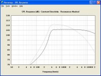
The attached screenprint shows the power response of a TD2001 driver on a Le Cléac'h horn (Fc = 320Hz, T = 0.8) for a constant diaphragm rms velocity of 10 cm/sec (black trace) compared to the same horn system with Eg = 2.83V (grey trace).
It is interesting that the HF response is significantly extended in the 'constant velocity diaphragm' case. Note that this applies to all horn types, not just Le Cléac'h horns.
Kind regards,
David
Attachments
Hello David,
Thank you a lot to study the possibility to use in Hornresp a constant velocity diaphragm.
Your simulation is very interesting as it may prove that some of the published measured parameters for the TD2001 (e.g.: mms or mmd) that are difficult for me to estimate through my own mesurement are somewhat eroneous...
Your simulation is also so near of my measurements (though your simulation is most probably "constant directivity power" while mine is on axis?) that it lead to thgink that the TAD TD2001 is really excellent and that the model of the TD2001 I developped for Hornresp has to me modified....
Best regards rfom Paris, France
Jean-Michel Le Cléac'h
David McBean said:
Hi Jean-Michel,
Currently the production version of Hornresp cannot simulate a constant velocity diaphragm (over the full frequency range).
In recent days though, I have been looking at the possibility of including such an option (as suggested by you in the Subwoofers Hornresp thread).
The attached screenprint shows the power response of a TD2001 driver on a Le Cléac'h horn (Fc = 320Hz, T = 0.8) for a constant diaphragm rms velocity of 10 cm/sec (black trace) compared to the same horn system with Eg = 2.83V (grey trace).
It is interesting that the HF response is significantly extended in the 'constant velocity diaphragm' case. Note that this applies to all horn types, not just Le Cléac'h horns.
Kind regards,
David
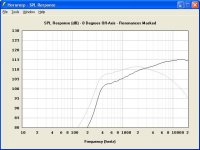
Jmmlc said:Though your simulation is most probably "constant directivity power" while mine is on axis?
Hi Jean-Michel,
Your assumption is correct.
The equivalent simulated on-axis pressure comparison is shown below (black trace = constant velocity, grey trace = Eg 2.83V).
Kind regards,
David
Attachments
Jmmlc said:Hello Earl,
2) If breakup was so important with the TD2001 it will show up on the impedance curve. What I see is that mounted on a Le Cléac'h horn the impedance curves of the TD2001 doesn't show any artifcats due to break up.
Jean-Michel Le Cléac'h
Hi ...
Thats not really true. Not all breakup will appear in the impedance and since the displacement falls with frequency ever lower and lower levels of breakup produce that same sound level. Hence it is nature for the breakup effect on the impedance to go away at HF, just as it does. An acoustically significant breakup need not show up in the electrical impedance.
Hello Earl,
Since few years I used to perform my impedance measurements using the logsweep + convolution method (Angelo Farina's method) on long duration sweeps.
This allow me to obtain high precision impedance measurement.
On the last loudspeaker I used to mesure I could identify many artifacts on the impedance curve one as high as 10380Hz that surely will be unoticeable using more conventional (and obsolete) measurements.
If a break up mode lead to some displacement of the diaphragm we can think that the current trhough the coil will be largely influenced (the energy conversion will be good...).
Best regards from Paris, France
Jean-Michel Le Cléac'h
gedlee said:
Hi ...
Thats not really true. Not all breakup will appear in the impedance and since the displacement falls with frequency ever lower and lower levels of breakup produce that same sound level. Hence it is nature for the breakup effect on the impedance to go away at HF, just as it does. An acoustically significant breakup need not show up in the electrical impedance.
Hello Jean-Michel,
please compare the first and the last measurements of my magnetostat. The impedance curve ist quite smooth except around 750Hz. The breakups, beginning from 5kHz up, are not visible in the impedance response.
Regards, Timo
please compare the first and the last measurements of my magnetostat. The impedance curve ist quite smooth except around 750Hz. The breakups, beginning from 5kHz up, are not visible in the impedance response.
Regards, Timo
bear said:Dunno, I like anything that improves the performance of a sub part or entire driver...
Having said that, obviously the proper and appropriate application is likely more important than any individual incremental technological improvement.
The radial phase slits are not new, RCA had drivers I think 50 years back now or more that used them. Cogent recently did a redux of that technology.
I'd be curious to see what benefits they actually have in their driver's performance.
_-_-bear
That is what I wanted to say. All Beryllium superiority should be related to the implementation. If a composite diaphragm does the same for less than a tenth of the cost why Be?
Somewhere in this thread I read something about a long build AlNiCo magnet that causes some issues with the phase plug design. Don't we have Neodym that is even stronger and magnetically "harder", not to forget its low weight?
18sound redesigned the phase plug combining anular and radial openings. The benefit is a smoother response even with standart diaphragms.
We are all no driver designers. From what experience or other insight we could estimate the reason for some irregularities and the right cure against it? Pioneers drivers seem to be a bit old fashioned, if the Be is taken out of the comparison. And if not, the Be still has to stand for example the 18sound nitride composite.
btw is this thread about costly drivers or is it about horns?
cheers
Jmmlc said:Hello Michael,
If one look to the on axis unequalized response curve of an axisymetric Le Cléac'h horn there is no such hole as with an axisymetric waveguide.
Eventually a small hole on the response curve may be seen at frequency over 14kHz and with angle over 15 degrees from the axis.
I attached a graph with frequency response curves at different angles for one of my TAD TD2001 mounted on a Le Cléac'h horn (Fc=320Hz T=0.8) applying on axis equalization.
Best regards from Paris, France
Jean-Michel Le Cléac'h
Thanks a lot - yes this behaviour I exactly was looking for.
Michael
gedlee said:
Hi LynnLynn Olson said:
I'm thinking the ultimate HF limit is a function of the throat area - and the "squeeze" or "pinch" you sometimes see in the throats of prosound horns is nothing more than a trick to extend the bandwidth by a few kHz at the cost of diffraction and time distortion.
I would completely agree with you here, its not only obvious from the products but it holds up to be true analytically. One has to be concerned with those things that are often done to "hold up" the high end.
Maybe I got you wrong, but I don't agree with the tenor of the message in the light of soongsc's contour.
There the "hold up the high end" wasn't done by intention – quite contrary – in fact its a notch on axis – coming up at non-axis only if you equalize for *flat* on axis.
Its pretty simply – you can't avoid diffraction and its influence on the sound field inside the horn – be it one way or the other – it always enters the picture especially when wave lengths get closer to contour dimensions (top end) – but there are other threads to head bang about that.
Also the distortion in the time domain is nothing to worry about - *if* you go the advanced active route.
May come back later with the impulse response plots for soongsc's contour – not much to see over the 0 10 20 30 40 deg angle – except that you literally could die for such clean and consistent impulses over such a wide coverage.
When I did the measurements I had to check back several times as I thought I'm gonna to store the same ones under different angles
")
What I would like to focus on here is that I see no possibility to increase upper bandwidth limit other than to "pitch" the throat below the wave length.
The question to me arises: are there already any horns that aim in the direction of the diffraction horns (meaning squeezed throat for uniform coverage *and* huge band width) that take into account an optimised transition from the pitch to the contour as soongsc has done?
(In a way the phase plug of a compression driver basically is the same thing - squeeze the displacement volume of a relatively large diaphragm area through a small throat *and* try to not mess up the wave front completely -amongst others)
And especially – how do such horns – if they exist (diffraction, biradial etc) – compare sonically.
I'm not so much after the horn theory (meaning gain maximising) nor after the wave guide theory (meaning HOM minimising) nor after flat FR but am looking for a "directivity control device" which should be as minimum phase as possible in the John Kreskovsky definition (over a as wide as possible room angle) to allow for advanced equalizing.
I'm also specifically interested how such horns sound if the irregularities at the top end are cut – meaning : is the main band width compromised by the strong pitch?

Michael
mige0 said:
The question to me arises: are there already any horns that aim in the direction of the diffraction horns (meaning squeezed throat for uniform coverage *and* huge band width) that take into account an optimised transition from the pitch to the contour as soongsc has done?
Michael
I thought that was what the drivers own "centerplug" was doing
Anyway, this "centerplug" changes the contour/transistion of the throath exit of driver
The angle you see may be far from the actual one, depending on the centerplug, of which I know little
But I suppose you know that, or maybe I have no clew
But thats how it looks to a simple mind
Lynn Olson said:
I'm thinking the ultimate HF limit is a function of the throat area - and the "squeeze" or "pinch" you sometimes see in the throats of prosound horns is nothing more than a trick to extend the bandwidth by a few kHz at the cost of diffraction and time distortion.
Nice to see You recovered. And You are still the same. What You wrote above is supported by Your feelings. Especially for the latter. Would You mind to figure out what is meant with the "cost of diffraction and time distortion" that have to be hold against "extend bandwidth by a few kHz"? That's the drama people like so much in Your writing - honest! It is simple, and it is grounded somhow, it seems to perpetuate ancient rules, not getting anything You want but trying. Compromize, but You go for the ultimate. That or nothing.
Great, and I mean it. People love You. But - would You mind to tell me some numbers regarding the diffraction/time thing? I'm curious to know what a Frensh or Texan horn could do for me.
so long, welcome back to the living

- Home
- Loudspeakers
- Multi-Way
- Jean Michel on LeCleac'h horns