I have been through many of these threads and the one common theme I see is that in order to effectively model an ML-TL you need MJK's worksheets. If someone could help me out I would be so appreciative. My head is hurting these last few days trying to figure out a simple way to do this. It all leads back to the worksheets.
The driver is a Seas ER18RNX
T/S:
re : 5.9
le: .67
Bl: 7.2
Fs: 37
Sd: 136cm2
Vas: 32l
Qms: 1.58
Qe: .39
Qt: .32
I'm looking for floor standers which is why I am not going with Zaph's design. And I figure if I am going with floor standers, why not reap the benefits of an ML-TL? It looks like this driver would be a good candidate but I just don't know where to put it in the enclosure, where to optimally put the port, what the port dimensions should be, how tall the box... A BR is easy, there is just no good way for an English Major such as myself to figure this out. Thanks.
Here's one ML-TL possibility
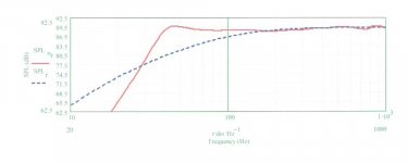
The attachment shows the system response for an ML-TL I modeled with Martin's ML-TQWT worksheet. I modeled a cabinet with INTERNAL dimensions of 6.5"W x 9"D x 40"H. The ER18's center is located 8" (internally) from the top. The mass-loading port can either be a 2.5"-diameter tube with its center 2" above the bottom of the 40" height, or it can be a 1"H x 5"W slot port located at the very bottom. Either type of port needs a length of 3" and can be located on either the baffle on the rear panel. I used a stuffing density of 0.75 lb/cu.ft. You'll need a total of 11 ounces of stuffing distributed uniformly by density in the top 26-27" of the cabinet. You'll see in the attachment that F3 is about 37-38 Hz. If you want it lower, the cabinet's depth and/or width could be increased to get a larger volume. I assumed you were intending this to be a MT with the tweeter located above the ER18 on the baffle. I modeled arbitrarily with 0.5 ohms in series with the ER18 to represent likely d.c. resistance of crossover inductor(s) in series with this driver. The graph depicts the likely SPL output with a 2.83-volt input.
The attachment shows the system response for an ML-TL I modeled with Martin's ML-TQWT worksheet. I modeled a cabinet with INTERNAL dimensions of 6.5"W x 9"D x 40"H. The ER18's center is located 8" (internally) from the top. The mass-loading port can either be a 2.5"-diameter tube with its center 2" above the bottom of the 40" height, or it can be a 1"H x 5"W slot port located at the very bottom. Either type of port needs a length of 3" and can be located on either the baffle on the rear panel. I used a stuffing density of 0.75 lb/cu.ft. You'll need a total of 11 ounces of stuffing distributed uniformly by density in the top 26-27" of the cabinet. You'll see in the attachment that F3 is about 37-38 Hz. If you want it lower, the cabinet's depth and/or width could be increased to get a larger volume. I assumed you were intending this to be a MT with the tweeter located above the ER18 on the baffle. I modeled arbitrarily with 0.5 ohms in series with the ER18 to represent likely d.c. resistance of crossover inductor(s) in series with this driver. The graph depicts the likely SPL output with a 2.83-volt input.
Attachments
pkitt,
Thank you very much. The graph looks very promising and my only concern is that they may end up a little boomy when room gain is taken into account. Would you recommend dealing with this in the crossover, or would a slightly lower box volume tame that roll off a little?
-Tim
Thank you very much. The graph looks very promising and my only concern is that they may end up a little boomy when room gain is taken into account. Would you recommend dealing with this in the crossover, or would a slightly lower box volume tame that roll off a little?
-Tim
netcastle said:pkitt,
Thank you very much. The graph looks very promising and my only concern is that they may end up a little boomy when room gain is taken into account. Would you recommend dealing with this in the crossover, or would a slightly lower box volume tame that roll off a little?
-Tim
If you reduce the cabinet depth to 7" and make the port 4" long, F3 rises to 40 Hz (you only need a little over 8 ounces of stuffing in the same space with this smaller cabinet volume). Unless you over-stuff to force the shape of the knee to be more rounded and the initial roll-off a bit slower, which may have negative side effects elsewhere, there's not much you can do IMO outside of the crossover to change the shape of the curve below the knee for these drivers.
pkitt,
Thank you for your input. I am going to take your suggestions and build this cabinet. The more I thought about it, I could only imagine the size of an inductor needed to tame a low end roll off, so I guess I agree as well. I will post back when I get this done and post some results.
-Tim
Thank you for your input. I am going to take your suggestions and build this cabinet. The more I thought about it, I could only imagine the size of an inductor needed to tame a low end roll off, so I guess I agree as well. I will post back when I get this done and post some results.
-Tim
netcastle said:
I'm looking for floor standers which is why I am not going with Zaph's design.
And I figure if I am going with floor standers, why not reap the benefits of an ML-TL?
Hi,
There are very good reasons to go with Zaphs design in any sort of box.
FWIW if you want less boomy bass you make the box bigger, not
smaller, and/ or tune the port or ML (in the TL) lower than "flat"
would indicate.
Do not ignore Zaphs measured parameters.
http://www.geocities.com/woove99/Spkrbldg/ER18RNX_2Way.htm
or WJ's tuning options :
2) You want to build the design in a floorstanding cabinet, which
means a little more baffle gain due to the extended baffle height
(see the effect of using a tall baffle on frequency response)
Þ Use my default crossover;
") /sreten.
/sreten.http://www.rjbaudio.com/Audiofiles/FRDtools.html
http://www.geocities.com/woove99/Spkrbldg/DesigningXO.htm
http://www.zaphaudio.com/
http://www.rjbaudio.com/projects.html
http://www.geocities.com/woove99/Spkrbldg/
http://www.troelsgravesen.dk/Diy_Loudspeaker_Projects.htm
http://htguide.com/forum/forumdisplay.php4?f=39
http://www.humblehomemadehifi.com/
Attachments
sreten said:
Hi,
There are very good reasons to go with Zaphs design in any sort of box.
FWIW if you want less boomy bass you make the box bigger, not
smaller, and/ or tune the port or ML (in the TL) lower than "flat"
would indicate.
sreten,
Thank you for your advice. I have looked into zaph's designs and respect his contributions to this community. I have also heard excellent reviews of the
sr71. In fact, I had intended to build these, but a floor stander fits well into my room and when I started learning about TL's I couldn't resist. Can you blame me
In response to your comment, are you suggesting that the bigger box pkitt modeled will be the better option for accurate lowend reproduction (I think that is what you are saying - and they are the ones I would like to try)? Additionally, if I place these near a wall (which I must) I should go with a significantly reduced baffle step to accommodate the boundary and baffle reinforcement? I am also using the H1189 (TDFC). Will the reduced baffle step crossover from zaphs design work?
-Tim
Do not ignore Zaphs measured parameters.
http://www.geocities.com/woove99/Spkrbldg/ER18RNX_2Way.htm
or WJ's tuning options :
Or these? (I got hung up on the first part of your post. I'll have a look here as well).
Hi,
Both designs use the 27TDFC aka the H1189, so no problem there.
The ER18RNX would work well in a 20L to 22L vented floorstander,
an arrangement like the following could lower the overall hieght :
http://www.humblehomemadehifi.com/Tempo.html
Adjust hieght for the best axis, the depth for internal volume.
(could be built with a vertical back if you so inclined, but harder).
IMO it should be tuned low, 33Hz to 35Hz for best in-room bass.
TL's, or MLTL's AFAIK to work properly need more internal volume,
usually too much for a sensibly vented box, but is a way of getting
more bass ..... but possibly e.g. in 3 way you be better off using
that volume with a bigger bass driver vented low down than usual.
TBH I'm no expert on MLTL's and suppose e.g. that the Tempo
above depending on the stuffing strategy would act like a MLTL.
FWIW pkitt's numbers indicate a ~ 38L cabinet tuned to ~ 45Hz,
but presumably these numbers are based on the given parameters,
which in particular have higher Vas than measured by Zaph.
AFAICT MLTL's are very different to TL's, so if your after classic TL
bass then you'd need a folded line, I'd suggest a 4 to 5:1 taper.
http://www.quarter-wave.com/TLs/Alignment_Tables.pdf
http://www.quarter-wave.com/TLs/Alignment_Tables_Calculator_3_3_09.xls
Cabinet similar to this :
http://www.seas.no/images/stories/diykits/pdfdataheet/thor_cab.pdf
/sreten.
Both designs use the 27TDFC aka the H1189, so no problem there.
The ER18RNX would work well in a 20L to 22L vented floorstander,
an arrangement like the following could lower the overall hieght :
http://www.humblehomemadehifi.com/Tempo.html
Adjust hieght for the best axis, the depth for internal volume.
(could be built with a vertical back if you so inclined, but harder).
IMO it should be tuned low, 33Hz to 35Hz for best in-room bass.
TL's, or MLTL's AFAIK to work properly need more internal volume,
usually too much for a sensibly vented box, but is a way of getting
more bass ..... but possibly e.g. in 3 way you be better off using
that volume with a bigger bass driver vented low down than usual.
TBH I'm no expert on MLTL's and suppose e.g. that the Tempo
above depending on the stuffing strategy would act like a MLTL.
FWIW pkitt's numbers indicate a ~ 38L cabinet tuned to ~ 45Hz,
but presumably these numbers are based on the given parameters,
which in particular have higher Vas than measured by Zaph.
AFAICT MLTL's are very different to TL's, so if your after classic TL
bass then you'd need a folded line, I'd suggest a 4 to 5:1 taper.
http://www.quarter-wave.com/TLs/Alignment_Tables.pdf
http://www.quarter-wave.com/TLs/Alignment_Tables_Calculator_3_3_09.xls
Cabinet similar to this :
http://www.seas.no/images/stories/diykits/pdfdataheet/thor_cab.pdf
/sreten.Instead of starting a new thread, I am going to bump this for my question. I am also interested in using the Seas woofer mentioned above in a quarter wave design.
Can someone please help me with the design of an ML-TL? Box size is not a big concern, but I do have some requirements and goals:
The design listed above is too peaky for my tastes. I prefer flat response or even a slight roll-off to prevent boominess. Will an increase in stuffing help in this department? Thanks.
Can someone please help me with the design of an ML-TL? Box size is not a big concern, but I do have some requirements and goals:
- Overall cabinet width of 9 inches
- Woofer located 12 inches down from the top surface, including wood thickness
- Extension to around 40hz in room
The design listed above is too peaky for my tastes. I prefer flat response or even a slight roll-off to prevent boominess. Will an increase in stuffing help in this department? Thanks.
Sorry, I suppose that would helpOK, your woofer location is very specific, but with no height frame of reference..........
GM
This will be a 2-way design using a 6 inch waveguide above the woofer. Hence the distance calls for 12 inches below the top surface. I am simply using the same width and placement dimensions of the bookshelf cabinet to turn it into a floorstanding speaker.
I am flexible with the height. Anything from 40" to 48" maximum height to the top surface will work fine. This will make the woodworking a bit easier for me.
If it's too much trouble, I can simply make a dummy cavity below the bass reflex design to make it freestanding. I am not sure how long it takes to design an MLTL, but I don't want to take too much of someone's valuable time
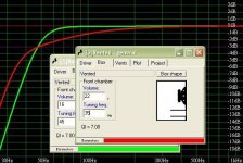
OK, this driver's Vas is too low for a simple MLTL with good output to 40 Hz without being a bit 'peaky' (looks like a T/S max flat alignment), especially since I can't slide the driver further down the pipe, so heavily damping both the cab and the vent will be required to get the desired critically damped response which will lower its LF output.
Half space sim, acceptable?
GM
Half space sim, acceptable?
GM
Attachments
Response appears to be very similar to the vented enclosure modeled in the original SR71 design seen here: Zaph|Audio - ZA-SR71
As you mentioned, I suppose the driver parameters and the limitations on placement are the culprits. Would you recommend building the MLTL or the 14 liter vented cabinet tuned to 44hz? Thank you very much for your help.
As you mentioned, I suppose the driver parameters and the limitations on placement are the culprits. Would you recommend building the MLTL or the 14 liter vented cabinet tuned to 44hz? Thank you very much for your help.
You're welcome!
Dims i.d. assuming ~0.75" material thickness, BB ply or similar recommended:
L = 46.5"
WxD = 7.5" x 6.25"
zdriver = 11.25"
zport = 3" dia. x 4" long pipe near/at the bottom, so will either need to be side exit or use an elbow
Strictly for reference: 0.2 lbs/ft^3 polyfil simmed in the cab and 0.4 lbs/ft^3 in the vent.
Please let us know how it turns out, damping used.
GM
- Status
- This old topic is closed. If you want to reopen this topic, contact a moderator using the "Report Post" button.
- Home
- Loudspeakers
- Multi-Way
- Noob - I need help putting a specific driver in an ML-TL