In this application there doesn't seem much to choose between an OPA2134 and a NE5532.
D Self's distortion tests indicates that even the distortion figures are similar when tested under similar conditions. The low bias current of the OPA isn't important here and dc supply currents ( very important ) are similar.
However the dual NE5532 chip cannot be used with a gain of less than 5 while you can do that with the single chip NE5534 with a compensating capacitor. So in the circuit shown by Linkwitz with a gain of x3 , the dual NE5532 cannot be used. The NE 5534 with suitable comp cap should be OK. The data sheet says the 5534 is internally compensated for a gain of x3 . Maybe an external 47pF comp cap gives you a stable unity gain circuit if one needs that.
A negative rail will incresase the maximum clean PPK signal that one can get out of the opamp. With a mic wired as Linkwitz has shown it can increase the spl handling capability of the mic capsule and the output with a WM-61 module with an opamp with a gain of about 3 appears to be 40mV @ 100dB spl. At 140dB spl that is about 11.3 volts ppk. So a single 9 V supply cannot do that.
The modified mic needs a -ve 9 volts for bias as seen on the Linkwitz site.
But then again maybe a 140 db capability is not required and so it makes things much simpler.
The 555 ( alternative easily availabe chip ? ..7555 ?) circuit looks interesting . It might be just worth trying but as infinia suggested it might require 'time' which always seems to be in short supply!
Note:The CMOS version of the 555 is a better bet. The standard 555 appears to have large current spikes compared to the CMOS version. I haven't checked this out but read about it somewhere.
blah! complicateddddd. now I'm just going to do the linkwitz circuit and x2 with a opa2132 in the center..
Absolutely !
But you did learn a few new things along the way ....!
Note: an OPA 2134 should be enough and it costs less than a OPA2132 .
They won't be doing anything unless the two batteries have different voltages. You don't need a splitter for one battery unless you're really tight on board space.nukaidee said:but since i have the rail ic's comming as well, can't I just put those to use? will it have any effect on the quality? or am I still not understanding rails.. sigh
This must be the simplest application using one dual chip ( OPA2130 etc ) one 9 V battery ,two caps and some resistors.
The output could be taken out between the opamp output and the 'virtual' ground . Apart from the protective series 100 ohm resistor there would be no output coupling capacitor. Or if the battery 0V is taken as ground then you would need a coupling cap. An electrolytic 10uF 16 V cap would be fine. + terminal going to the opamp output terminal.
The mic capsule would need a coupling cap. A non polar is best as one is not sure what the polarity of the voltage is on it's terminal wrt to the opamp input which is at 1/2 supply voltage ( 4.5 V ). A 0.22uF cap gives -0.5 db at 20 Hz or a 0.47uF cap gives -0.1db at 20 Hz. Both should be fairly small caps.
Edit:
We probably need a decoupling cap between the virtual earth and battery 0 V terminal. A 10uF 16V elco cap might be OK unless a film is required for better performance at hf/rf . Best way is to try it out. A smd board would come out really small.
Attachments
As long as the bias is higher than the maximum Vpp of the cap, the cap is always going to see a lower voltage on the mic side, no?ashok said:
The mic capsule would need a coupling cap. A non polar is best as one is not sure what the polarity of the voltage is on it's terminal wrt to the opamp input which is at 1/2 supply voltage ( 4.5 V ). A 0.22uF cap gives -0.5 db at 20 Hz or a 0.47uF cap gives -0.1db at 20 Hz. Both should be fairly small caps.
EDIT: Might be higher, on your schematic.
Well, one could always connect a wm-61 to a 9V supply with a 10 K resistor and see what the voltage is between ground and the mic/resistor junction. Then use an electrolytic cap and align it with the polarity that is indicated.
If the junction is less than 4.5 volts then cap plus goes to the opamp input and vice versa.
If the junction is less than 4.5 volts then cap plus goes to the opamp input and vice versa.
Couples (connects) AC to block DC. Input caps tend to be coupling caps.nukaidee said:uh. whats a coupling cap? i never understood what they were used for.
http://en.wikipedia.org/wiki/Capacitive_coupling
I'll let you know when my electrolytic fries.ashok said:Well, one could always connect a wm-61 to a 9V supply with a 10 K resistor and see what the voltage is between ground and the mic/resistor junction. Then use an electrolytic cap and align it with the polarity that is indicated.
If the junction is less than 4.5 volts then cap plus goes to the opamp input and vice versa.
Anyway, Linkwitz has a polarized cap as an input from the WM-61a.
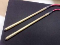
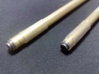
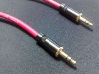
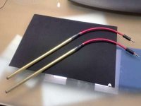
well I hope you guys enjoy photos as much as I do. my stereo pair is done. I only could match them by resistance. Then I did the linkwitz mod on them. the tubing is brass, mogami mini starquad cable, and gold neutrik ends. clear and black heatshrink all over, stuff with cotton.
Sorry about the quality, taken with my phone. Spent about 4 hours making these
Sorry about the quality, taken with my phone. Spent about 4 hours making these
Attachments
- Status
- This old topic is closed. If you want to reopen this topic, contact a moderator using the "Report Post" button.
- Home
- Loudspeakers
- Multi-Way
- wm-61 measuring mic