hi
i own soundeasy 14 given to me by a friend
i have jigglimg with this software for about a week .iam doing an
impedance measurement for a 5' inchi woofer.i have done everything
according to help manual by music and design.iam not getting the proper graph of spl/phase vs frequency.the curve is not rising at higher frequency.because of which it is giving error
http://i43.tinypic.com/f447px.jpg
here are the screen shot step by step
http://i40.tinypic.com/153oe0w.jpg
http://i43.tinypic.com/2r7vs69.jpg
http://i43.tinypic.com/bhlfzd.jpg
using 10 ohm series resistor with driver.connecting my sound card with a 100k passive control in between the amp and sound card.
amp is based on tda2030 .using the probes with 47/22k resistors for line in.
i have checked with these setting of preferences too
here is the screen shot of my preferences
http://i39.tinypic.com/24o2cs2.jpg
iam pulling my hair
ravs
pleasehelp
I've found that hair pulling is normal with SoundEasy.
I noticed in your first pic that you have Re expressed as 7-3 instead of 7.3. Not sure if that would have any effect.
The main difference I see is your impulse response looks different than mine. Mine swings up and down equally while yours only seems to go down.
I'd double check your connections. I'd also be tempted to try it without the attenuator, setting your SoundEasy output level appropriately.
Edit: PREFERENCES!!!!
I think I just found your problem. In preferences you have your freq range set to only 5,000Hz. Bump this up past 20k.
hi ultrachrome
i change the frequency from 5000 to 20000 and then to 50000 from non linear screen-frequency range in preferences but that didnt made any difference the impedance graph is still the same
the imp curve shoud similar to this one
http://i41.tinypic.com/11rtdeo.jpg
so what next now
thanks
ravs
i change the frequency from 5000 to 20000 and then to 50000 from non linear screen-frequency range in preferences but that didnt made any difference the impedance graph is still the same
the imp curve shoud similar to this one
http://i41.tinypic.com/11rtdeo.jpg
so what next now
thanks
ravs
slogan2112 said:Try measuring a resistor in place of the driver and see if you get a constant impedance vs frequency.
hi slogan2112
as you said to replace the driver with a resistor here it is with 15 ohm resistor
http://i39.tinypic.com/xngg0g.jpg
ravslanka said:hi ultrachrome
i change the frequency from 5000 to 20000 and then to 50000 from non linear screen-frequency range in preferences but that didnt made any difference the impedance graph is still the same
the imp curve shoud similar to this one
http://i41.tinypic.com/11rtdeo.jpg
so what next now
thanks
ravs
Yes, in retrospect, I see that my suggestion was in error.
Your resistor trace looks good.
After your resistor impedance trace, did you then again try measuring your woofer?
ultrachrome said:
Yes, in retrospect, I see that my suggestion was in error.
Your resistor trace looks good.
After your resistor impedance trace, did you then again try measuring your woofer?
hi ultrchrome
yes i did .first i calibrated with a 15 ohm resistor in place of a driver with 10 in series to the output of the amplifier.then replaced the 15r
with the driver.no difference.
screen
http://i42.tinypic.com/2dmhzdk.jpg
Re: did you dmm the resistor and trying different values
hi mcmahom48
i have tried 3 different drivers with different re measured with dmm
5.3 ohm.3.6ohm,7.3ohm.here is cabling diagram.i have tried inveting data and reference channel in preferences.
ravs
mcmahon48 said:and on the Re did you also dmm it and try some different values around the Re these software oriented are very touchy
also make shure that you have a cabling diagram you may want to have your friend walk you through it
hi mcmahom48
i have tried 3 different drivers with different re measured with dmm
5.3 ohm.3.6ohm,7.3ohm.here is cabling diagram.i have tried inveting data and reference channel in preferences.
ravs
Attachments
Have you tried a loop test? That is, using one output from one channel of your sound card, connect it directly (no amp or preamp in the circuit) to the L and R sound card inputs using a Y connector. Then take an SPL measurement (not impedance). Lease the start of the window at zero. You should see flat response.
What I see in your measurements looks as if one channel of you sound card has rolled off high frequency response. You appear to be doing everything correctly.
What I see in your measurements looks as if one channel of you sound card has rolled off high frequency response. You appear to be doing everything correctly.
john k... said:Have you tried a loop test? That is, using one output from one channel of your sound card, connect it directly (no amp or preamp in the circuit) to the L and R sound card inputs using a Y connector. Then take an SPL measurement (not impedance). Lease the start of the window at zero. You should see flat response.
What I see in your measurements looks as if one channel of you sound card has rolled off high frequency response. You appear to be doing everything correctly.
hi john k
here is spl measurement with loopback connection only 1 channel connected o both line in
http://i39.tinypic.com/24z9e29.jpg
ravs
ravslanka said:
hi john k
here is spl measurement with loopback connection only 1 channel connected o both line in
http://i39.tinypic.com/24z9e29.jpg
ravs
Hi rav, this is Jay. Try a loopback test on your test amp now. Put a Y connector on your test amp's input and connect the sound card's output and the ref probe to it. Then connect the test probe to your jig and measure the amp's output.
One last thing; Many users do not make the connection from the probes to the signal ground in their test jigs. On my system, this didn't matter, but it may make a difference on yours.
ultrachrome said:
Yes, in retrospect, I see that my suggestion was in error.
Your resistor trace looks good.
After your resistor impedance trace, did you then again try measuring your woofer?
Actually, the resistor trace should be flat, from min to max frequency. The resistor test is actually telling you 3 things, your sound card's freq. response, your test amp's freq response, and the value of the test resistor. The reqsponses are added together, so you can't be sure which is causing a problem, but it is still useful information.
If you choose a wire-wound resistor to test, you may see a slight drop-off in impedance at high frequencies (above 10 kHz) if the resistor has a significant amount of inductance.
lhwidget said:
Hi rav, this is Jay. Try a loopback test on your test amp now. Put a Y connector on your test amp's input and connect the sound card's output and the ref probe to it. Then connect the test probe to your jig and measure the amp's output.
One last thing; Many users do not make the connection from the probes to the signal ground in their test jigs. On my system, this didn't matter, but it may make a difference on yours.
lhwidget said:
Actually, the resistor trace should be flat, from min to max frequency. The resistor test is actually telling you 3 things, your sound card's freq. response, your test amp's freq response, and the value of the test resistor. The reqsponses are added together, so you can't be sure which is causing a problem, but it is still useful information.
If you choose a wire-wound resistor to test, you may see a slight drop-off in impedance at high frequencies (above 10 kHz) if the resistor has a significant amount of inductance.
hi lhwidget
good to find you over here
here is amp loopback test
http://i44.tinypic.com/2ujtvsz.jpg
next with with wirewound imp
ravs
and here is
imp curve with 11.1 ohm wirewound test resistor under dut
http://i42.tinypic.com/se2kit.jpg
imp curve with 11.1 ohm wirewound test resistor under dut
http://i42.tinypic.com/se2kit.jpg
This is not an amp or wire wound resistor problem, unless the amp has a flating ground? Ahigh inductance resistor whoud show Z rising with frequency not decreasing.
The SPL loop back looks ok.
The next question is about cables and leads and probes. First try reversing the probes. That is, change move the probe on the In cable to the Ref cable and vise versa. If one of the probes is not correctly made it could interact with the cable capacitance and give the high frequency roll off. Also, look for poor grounds and make sure the interconnects for the measurement are exactly the same.
john k... said:This is not an amp or wire wound resistor problem, unless the amp has a flating ground? Ahigh inductance resistor whoud show Z rising with frequency not decreasing.
The SPL loop back looks ok.
snip
Thank you John, on my way to work, after posting my thoughts, I realized I had it backwards... Not enough coffee this morning.
ravslanka said:
hi john k
here is spl measurement with loopback connection only 1 channel connected o both line in
http://i39.tinypic.com/24z9e29.jpg
ravs
Please do that following and post the results of loop back.ravslanka said:
hi lhwidget
good to find you over here
here is amp loopback test
http://i44.tinypic.com/2ujtvsz.jpg
next with with wirewound imp
ravs
1. check "Show Phase"
2. set window to "rectangular"
3. set smoothing to "none"
soongsc,
I think you may have hit the cause in your earlier post. Latency issues/problems. I tried this freeware program:
http://www.thesycon.de/eng/free_download.shtml
It's called DPC latency checker (you may know a better one). I found something on my laptop that grabbed the system every minute or so (I suspect the infra red port).
I created a new hardware profile with the following turned off:
1) on-board sound chip
2) ethernet port
3) wireless port
4) I-R port
5) parallel port
6) serial port
I think this may help ravslanka, it cleared up two things on my laptop:
1) Occasional measurements that didn't make sense (obviously incorrect imp & SPL measurements taken when the offending device grabbed the system)
2) Before turning everything off with the second hardware profile, even when I got seemingly good results, the impedance would either drop on the high end, or not rise as high as it should have. Not as much as your impedance plot rav, but in the same way.
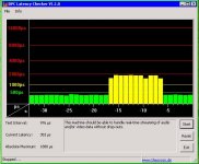
The attached pic is the obvious latency problem showing on my laptop. It took 1 to 2 minutes for it to show.
Just another thought (follow soongsc's & John's recommendations first)
Jay
I think you may have hit the cause in your earlier post. Latency issues/problems. I tried this freeware program:
http://www.thesycon.de/eng/free_download.shtml
It's called DPC latency checker (you may know a better one). I found something on my laptop that grabbed the system every minute or so (I suspect the infra red port).
I created a new hardware profile with the following turned off:
1) on-board sound chip
2) ethernet port
3) wireless port
4) I-R port
5) parallel port
6) serial port
I think this may help ravslanka, it cleared up two things on my laptop:
1) Occasional measurements that didn't make sense (obviously incorrect imp & SPL measurements taken when the offending device grabbed the system)
2) Before turning everything off with the second hardware profile, even when I got seemingly good results, the impedance would either drop on the high end, or not rise as high as it should have. Not as much as your impedance plot rav, but in the same way.
The attached pic is the obvious latency problem showing on my laptop. It took 1 to 2 minutes for it to show.
Just another thought (follow soongsc's & John's recommendations first)
Jay
Attachments
- Status
- This old topic is closed. If you want to reopen this topic, contact a moderator using the "Report Post" button.
- Home
- Loudspeakers
- Multi-Way
- help measurin imp in soundeasy