Hi,
There has been a 'Boxenklinik' article about the nautilus 804 in "Hobby Hifi", where they designed a new filter for it.
Interesting loudspeaker magazine.
Sorry, no scanner here.
I think you can buy back issues.
http://www.hobbyhifi.de/Archiv/07/04_07/04_07.html
I cannot remember if the original schematic was in the article.
The Nautilus 804 has 3 crossover boards - one for the tweeter, FST mid range unit and one for the 2 LF drivers.
All 3 crossover boards can be accessed by removing the LF drivers.
So the FST mid range unit does not need to be removed to get access to the mid or HF crossovers
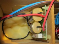
The HF crossover board has
L1 - small air core inductor
C1 - 4.7 uF length = 1 3/8"
C2 10 uF length = 1 3/4"
R1 = 2R2 11 watts - with Bennic inked as the make
My experience with commercial wire wound resistors - used for audio - is that they sound harsh.
A harsh sounding resistor, in series with a Nautilus metal dome tweeter, is less than ideal.
So replacing the 2R2 resistor with a Mills or Mundorf would probably improve the sonics.
Replacing the 4u7 cap with a Mundorf Supreme or Silver Oil would certainly make an improvement - however, I'll have to check if one will fit.
Another option maybe replacing it with a Mundorf EVO gold silver oil cap.
But have yet to hear the new EVO gold silver oil caps
Here is a photo of the Nautilus 804 HF board.
.
All 3 crossover boards can be accessed by removing the LF drivers.
So the FST mid range unit does not need to be removed to get access to the mid or HF crossovers
The HF crossover board has
L1 - small air core inductor
C1 - 4.7 uF length = 1 3/8"
C2 10 uF length = 1 3/4"
R1 = 2R2 11 watts - with Bennic inked as the make
My experience with commercial wire wound resistors - used for audio - is that they sound harsh.
A harsh sounding resistor, in series with a Nautilus metal dome tweeter, is less than ideal.
So replacing the 2R2 resistor with a Mills or Mundorf would probably improve the sonics.
Replacing the 4u7 cap with a Mundorf Supreme or Silver Oil would certainly make an improvement - however, I'll have to check if one will fit.
Another option maybe replacing it with a Mundorf EVO gold silver oil cap.
But have yet to hear the new EVO gold silver oil caps
Here is a photo of the Nautilus 804 HF board.
.
Attachments
ancestrale,
Unless you have the exact same drivers which I would doubt why would you want to clone that crossover? Just from the simple description of it it doesn't sound like anything special, actually sounds rather like a crude 1st order network. As for all the hype about oil filled whatever save yourself a lot of money and buy some good polypropylene capacitors and quality large gauge inductors.
Unless you have the exact same drivers which I would doubt why would you want to clone that crossover? Just from the simple description of it it doesn't sound like anything special, actually sounds rather like a crude 1st order network. As for all the hype about oil filled whatever save yourself a lot of money and buy some good polypropylene capacitors and quality large gauge inductors.
As for all the hype about oil filled whatever save yourself a lot of money and buy some good polypropylene capacitors and quality large gauge inductors.
Thanks for your response.
Moving from the original B&W Nautilus series from the 1990's, to the Diamond series,
B&W improved the crossover components to upper end Mundorf's in key locations.
They used regular MKP's in non critical locations.
With my B&W 603 s2's, I replaced the caps in series with the tweeter
with an AuriCap and a Mundorf Supreme.
The series resistor was replaced with a Mundorf metal oxide.
The AuriCap and Mundorf Supreme seem to complement each other quite well.
I made these changes one at a time, and each change, for whatever reason, reduced harshness.
As you've pointed out, an original intent, of opening up my N804's,
was to see if the inductors connected to the LF drivers, could be replaced
with ones that have a lower resistance.
However, looking at the LF board, I can't see any markings for the inductor values.
So they would have to be pulled out and their values measured.
I'd use a frequency sweep of an LCR circuit and find the resonance.
If they were to be replaced, almost certainly ferrous cores would be needed.
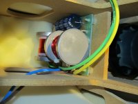
Here is a photo of the N804 LF crossover board.
Attachments
Uunderhill,
This is my opinion and I am sure there are as many of those and people who will answer this thread. If you want to improve the sound of your B&W speakers I would look at a few things. As you have seen B&W like most manufacturers look where they can cut corners. One is in the quality of the crossover components. I would think about air core inductors for an improvement and not an iron core inductor. This is a cost saving move, a larger wire diameter and no iron core will take the core saturation out of the picture that you now most likely have. Yes you would have to take the inductor out to get the value. If you really want to make a significant difference you would be much better off trying to add a Zobel network to the devices to flatten the impedance rise in the devices. The next move up as far as I am concerned in a passive crossover would be to go to 4th order crossover designs but that would be a major change and unless you can measure the speaker parameters that would be a shot in the dark. I can't help you go past this point as I don't have any specific information about the devices.
This is my opinion and I am sure there are as many of those and people who will answer this thread. If you want to improve the sound of your B&W speakers I would look at a few things. As you have seen B&W like most manufacturers look where they can cut corners. One is in the quality of the crossover components. I would think about air core inductors for an improvement and not an iron core inductor. This is a cost saving move, a larger wire diameter and no iron core will take the core saturation out of the picture that you now most likely have. Yes you would have to take the inductor out to get the value. If you really want to make a significant difference you would be much better off trying to add a Zobel network to the devices to flatten the impedance rise in the devices. The next move up as far as I am concerned in a passive crossover would be to go to 4th order crossover designs but that would be a major change and unless you can measure the speaker parameters that would be a shot in the dark. I can't help you go past this point as I don't have any specific information about the devices.
As you have seen B&W like most manufacturers look where they can cut corners. One is in the quality of the crossover components. I would think about air core inductors for an improvement and not an iron core inductor. This is a cost saving move, a larger wire diameter and no iron core will take the core saturation out of the picture that you now most likely have. Yes you would have to take the inductor out to get the value. If you really want to make a significant difference you would be much better off trying to add a Zobel network to the devices to flatten the impedance rise in the devices. The next move up as far as I am concerned in a passive crossover would be to go to 4th order crossover designs but that would be a major change and unless you can measure the speaker parameters that would be a shot in the dark. I can't help you go past this point as I don't have any specific information about the devices.
Thank you for your input.
Totally agree with you - I highly suspect the designers of these B&W's were required to cut corners
and tragically this occurred with the crossovers.
Unfortunately, there is little info available on modding the crossovers of N804's.
However, there is info on modding matrix 802's
B&W crossover rebuild
The crossover schematic for the N804's appears to be somewhat similar to that of the Matrix 802's.
On the Nautilus 804 LF crossover board, there is a 150uF electrolytic and a 0R33 resistor.
I highly suspect that these 2 components were used for a Zobel network.
The issue with Nautilus 804's is that |Z| >= 2.9 ohms
also, the phase angles become excessively challenging for an amp.
One solution may be to bi amp.
Maybe a small class A MOSFET power amp for the Mid and HF section.
and a huge bi polar push pull amp for the LF.
Another solution maybe to build the LF crossover section.
Which I am a nervous to do.
However, what if a totally new LF crossover was built and it was outside the cabinet ?
.
Uunderhill,
A correct Zobel, or conjugate network, will have a capacitor, inductor and resistor value, all at the speaker binding posts. The resistance of the inductor is added to the resistor value to compete the equation. To get it right you have to get the "Q" of the zobel to match the Q of the speaker in an inverse relationship. I suspect that what you are seeing with the capacitor and resistor is that is part of a second order filter and there is an inductor in the leg going to the speaker. I would say without seeing what you have that B&W did a real disservice to the overall sound of the speakers with the network you are describing. It would be very helpful if you could find someone who has actually tested the speakers by themselves, sans network so you could get a better idea of what you are looking at. You would probably be very surprised how much better the sound would be with a proper crossover for your speakers.
A correct Zobel, or conjugate network, will have a capacitor, inductor and resistor value, all at the speaker binding posts. The resistance of the inductor is added to the resistor value to compete the equation. To get it right you have to get the "Q" of the zobel to match the Q of the speaker in an inverse relationship. I suspect that what you are seeing with the capacitor and resistor is that is part of a second order filter and there is an inductor in the leg going to the speaker. I would say without seeing what you have that B&W did a real disservice to the overall sound of the speakers with the network you are describing. It would be very helpful if you could find someone who has actually tested the speakers by themselves, sans network so you could get a better idea of what you are looking at. You would probably be very surprised how much better the sound would be with a proper crossover for your speakers.
Uunderhill,
A correct Zobel, or conjugate network, will have a capacitor, inductor and resistor value, all at the speaker binding posts. The resistance of the inductor is added to the resistor value to compete the equation. To get it right you have to get the "Q" of the zobel to match the Q of the speaker in an inverse relationship. I suspect that what you are seeing with the capacitor and resistor is that is part of a second order filter and there is an inductor in the leg going to the speaker. I would say without seeing what you have that B&W did a real disservice to the overall sound of the speakers with the network you are describing.
It would be very helpful if you could find someone who has actually tested the speakers by themselves, sans network so you could get a better idea of what you are looking at. You would probably be very surprised how much better the sound would be with a proper crossover for your speakers.
Its been more than 20 years since I seriously looked at transfer functions.
However, this article seems to explain a Zobel network like you are describing
DIY Speakers Design Knowledge, Speaker Review, Loudspeaker: Zobel Network Design
I can't find much information on modding Nautilus speakers.
This is very surprising considering how many of these speakers must have been sold,
the quality of the drivers, and the beauty of the cabinets.
Certainly - B&W realized the need to use upgraded components with their diamond series.
Turns out a Nautilus 804 LF board is $80 - so rather than taking apart the crossovers,
it would be much safer just buying a single board and measuring the inductors in it.
Here is a complete list of the components on each of the 3 crossover boards on the N804's
HF Board
L1 - small air core
R1 - 2R2 - 11 watts - length = 1.9" commercial wire wound
C1 = 4u7 length = 1 3/8"
C2 = 10uF length = 1 3/4"
MF Board
L1 - air core
L2 - air core
C1 - 47uF - huge poly cap
C2,3 & 4 - 3u3 MKP or MKS caps (in parallel ???)
R1 - 2R2 - 30 watt - commercial wire wound
LF Board
L1 - wound on a ferrous bobin
L2 - wound on a ferrous bobin
C1 - 150 uF non polarized electrolytic
R1 - 0R33 - 11 watt - commercial wire wound
Qty 2 - ZZ11304 bass drivers
Uunderjhill,
Cut one wire before or after the inductor, measure the inductor and solder one wire back together. Couldn't take much and I don't see how you would damage your crossover. But this is only relevant if all you are trying to do is replace the inductor with another of the same value. If you could find someone in your area that could actually measure the individual speaker T/S parameters then you could get some help in making a much nicer crossover for your speakers. I know there are many people here on the website that are from up there in the North, perhaps you just have to ask that simple question. Many people here on the forum would love the challenge I would bet.
Cut one wire before or after the inductor, measure the inductor and solder one wire back together. Couldn't take much and I don't see how you would damage your crossover. But this is only relevant if all you are trying to do is replace the inductor with another of the same value. If you could find someone in your area that could actually measure the individual speaker T/S parameters then you could get some help in making a much nicer crossover for your speakers. I know there are many people here on the website that are from up there in the North, perhaps you just have to ask that simple question. Many people here on the forum would love the challenge I would bet.
Uunderhill,
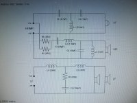
That is a much more refined crossover you just posted. It is a 3rd order design, I am not a great fan of those because of the phase shift at crossover point but this is a much more thought out design. Are the speakers in the two different speaker cabinets the same? If not you are just taking a chance that this crossover will work for you. It just seems that you are working backwards as far as improving what you actually have. I still think you need someone to check your speakers without the crossovers attached and start from there.
That is a much more refined crossover you just posted. It is a 3rd order design, I am not a great fan of those because of the phase shift at crossover point but this is a much more thought out design. Are the speakers in the two different speaker cabinets the same? If not you are just taking a chance that this crossover will work for you. It just seems that you are working backwards as far as improving what you actually have. I still think you need someone to check your speakers without the crossovers attached and start from there.
If you could find someone in your area that could actually measure the individual speaker T/S parameters then you could get some help in making a much nicer crossover for your speakers. I know there are many people here on the website that are from up there in the North, perhaps you just have to ask that simple question. Many people here on the forum would love the challenge I would bet.
The part Numbers for the drivers in the N804's are:
Qty 1 - ZZ10531 - metal dome tweeter
Qty 1 - FST mid range - ZZ10531
Qty 2 - bass units ZZ11304
I checked and both bass drivers have the same part number
Looking carefully at the LF crossover - it looks like the 2 bass drivers are connected in parallel.
I know Zero about T/S paramemters, however, here is a great little website that explains how to measure them.
Unfortunately, I don't have a sine wave generator.
T-S Parameter Calculator
Even if I had a sine wave generator, or could find someone who could take the measurements,
getting the FST mid range out or tweeter out would be hugely problematic.
So to take a measurement, the test equipment would have to be brought to the speaker, and the wires cut at the crossover.
However - on the positive side - because there are 3 separate crossover boards and there are bi-wiring terminals,
so a new LF board could be rebuilt totally outside the speaker.
Have a look at Troel's website, where he fine tunes the crossover of the 3 Way Classic, outside of the speaker.
In this case, he passes the wires through the port.
3-Way Classic
However, in the case of the N804, this could be done just using the bass bi-wiring terminals.
.
Uunderhill,
That is a much more refined crossover you just posted. It is a 3rd order design, I am not a great fan of those because of the phase shift at crossover point but this is a much more thought out design. Are the speakers in the two different speaker cabinets the same? If not you are just taking a chance that this crossover will work for you. It just seems that you are working backwards as far as improving what you actually have. I still think you need someone to check your speakers without the crossovers attached and start from there.
There is no real way to get the N804 crossover schematic
without pulling the boards out - which I am chicken (or wise) about doing.
So I can only speculate that the Matrix 802 and N804 crossovers are very similar.
However, the component list for both crossovers is nearly identical.
Would it be OK just to get the T/S parameters of just the bass drivers only ?
OR would the parameters of all 3 driver types be needed ?
I can not believe no one hasn't done this before.
.
If you know for sure that the two different models use the same identical bass speaker that would be all that you need to work on a new crossover for the bass section. I understand about delving into the speakers to check things and not wanting to make a mess of things. Do the speakers come out of the enclosure or are they like some of the other B&W made as part of the enclosure without a speaker frame? If you can just unscrew them I would be surprised if the wires would be soldered onto the terminals of the speakers.
- Status
- This old topic is closed. If you want to reopen this topic, contact a moderator using the "Report Post" button.
- Home
- Loudspeakers
- Multi-Way
- B&W 804 Nautilus, crossover schematic filter