The JBL 375 (same as the JBL 2440 other than color) uses a 4" diaphragm and a large back chamber.I was thinking of DIY a compression driver.
What accounts for the low Fs of the 375 driver compared to a modern low cost ones where Fs is above 1Khz?
It was designed in the days when two way usually meant 500 Hz crossovers.
Many current drivers are designed for use with crossovers one or two octaves higher, but there are still many compression drivers made that can be used to 500 Hz or lower.
Phenolic diaphragm PA type 1" exit drivers like the Selenium D250X can work for such low crossovers.Which modern CD work to 500Hz or lower?
Preferably lower cost ones for 1" throat.
No, inexpensive + 1" exit + "hifi" from 500-20K don't add up well.The Selenium D250X is for midrange use and not the highest in fidelity whereas the old Altecs and JBL's did 500Hz and up. Do you have another suggestion not Altec or JBL?
If I was looking for 500 Hz response up from a compression driver, I'd use a 1.5" exit 3" diaphragm, not a 1.75" diaphragm.How about modern, expensive, 1" exit 500-20k?
I use the EVDH1AMT, there may be other new drivers that sound better, I wish I had the budget to do comparisons with current drivers.
I still prefer the sound of small cone midrange to the DH1AMT below 1000 Hz.
Which modern CD work to 500Hz or lower?
Preferably lower cost ones for 1" throat.
I'd like a car that can do zero to sixty in under four seconds, preferably lower cost
and
I'd like to data a woman who looks like Kim Kardashian, but enjoys listening to me blather on about loudspeakers
While you're working on those two, I'll find you an inexpensive compression driver that fits your requirements
")
(hint : none of the above exists)
Last edited:
I'd be willing to DIY a compression driver. Has anyone ever tried that?
Totes. It's the whole reason I was trying to figure out the Thiele Small of my DE25.
DIY compression drivers are very much do-able, particularly thanks to the hard work of David McBean
Which modern CD work to 500Hz or lower?
Preferably lower cost ones for 1" throat.
You have to go to a 2" driver for that, based on all the data sheets I've read.
Maybe the B&C DE250 is better than the 802 after all.
I want to use it with a 811B, it might work well above 1kHz.
The B&C DE250 on the 811B will go lower than the DE250 on the smaller ME45 horn.
iirc i've seen jbl 243* data somewere on audioheritage..
close enough..JBL 2441 Hornresp input screen shot here:
http://www.diyaudio.com/forums/attachment.php?s=&postid=1536087&stamp=1213172475
How close do you believe these values are to real life?..
Attachments
Last edited:
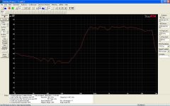
very unexpected imp. graph without back chamber!..More data here: Audio Psychosis • View topic - Simulating a B&C DE25
did you fixed the diaphragm during measurement? in what way? i have similar china 3"..
2431hiirc i've seen jbl 243* data somewere on audioheritage..
Attachments
Last edited:
Can anyone confirm which parameters of those posted for the simplified models are actuals? Obviously the remaining parameters need to be contrived.
The contrived parameters are likely to be quirky because a typical compression driver has a second front chamber which is connected via the gap (slit) between the voice coil former and magnet. The Akabak model I have been playing with is EXTREMELY sensitive to the flow properties of this gap. The simple model assumes only a single chamber between diaphragm and perforated phase plug
The Akabak compression driver model uses 21 parameters. I could only find 2 parameter values quoted by B&C (Re and Le). The other 19 have to be guessed unless someone can provide them. Matching the SPL and Impedance values for the DE250 on a B&C ME45 waveguide has been fun but also frustrating because a few more actual values, physical or electrical measurements, would make things much easier. Trying to adjust 19 interactive parameters is akin to juggling jellyfish!
For those who wish to play with the complex Akabak model the script is given below.
It’s a fairly close match to graphs on the B&C site. Matching data generated using the strategy suggested by Earl would be better but I haven’t yet commissioned my test gear.
In an ideal world I would also prefer to model drivers ( using any suitable theoretical model) before deciding to buy.
The simple model recommended has the obvious advantage of using far less parameters. Again, it would be great to know which parameters could use actual values.
| AkAbak script - DE250 Compression driver
| Parameters preceeded by ...... need to be defined
Def_Const
{ Ree=6.3; |Voice coil resistance [ohm] ......(Re)
Le=0.11e-3; |Voice coil inductance [H] ......(Le)
Bl=6.0; |Motor conversion factor F=Bl*i [Tm]......(BL)
Mms=1e-3; |Mechanical mass [kg] ......(Mms)
Rms=0.4; |Mechanical resistance [Ns/m] ......(Rms)
Cms=30e-6; |Mechanical compliance [N/m] ......(Cms)
dDi=40e-3; |Diameter centre diaphragm [m] ......(Diam of inner magnet)
dDa=47e-3; |Diameter outer diaphragm [m] ......(Diam of outer chamber)
Hi=1.0e-3; |Eff. height of outer chamber under the ring ......(gap between diaphragm and phase plug)
Ha=4.5e-3; |Eff height of outer chamber under the ring ......(Averaged height of annular chamber)
ds=0.20e-3; |Slit between voice coil and magnet ........(Annular gap between magnet and voice coil former)
ls=11e-3; } |Length of voice coil path .......(Length of annular gap)
System 'DE250'
|Voice coil (frequency-non-linear resistance and reactance)
Impedance 'Ze' Node=1=2 Z={ Ree*(1 + f/35e3) + j*(w*Le)^0.6; } |.......(f/? , w*Le^?)
|Motor
Gyrator 'Gy1' Node=2=0=3=4 Bl={Bl}
|Reverse side with enclosure
Coupler Node=4=0=100 dD={dDa}
Enclosure 'Eb' Node=100 Vb=20cm3 Qb/fo=0.005 | .......(Vb , Qb/fo)
|Mechanical part (Mms frequency depending, cut-off at ? kHz)
Impedance 'Zms' Node=3=5
Z={ wo=2*pi*15000; Zms=Rms + j*(w*Mms/(1 + w/wo) - 1/(w*Cms)) } | ......(2*pi*?)
|Outer diaphragm (ring) with cavity
Coupler Node=5=6=200 SD={ pi*(sqr(dDa/2)-sqr(dDi/2)) }
Enclosure 'Efo' Node=200 Vb={ SD=pi*(sqr(dDa/2)-sqr(dDi/2)); Vb=SD*Ha }
|Centre diaphragm with compression chamber
Coupler Node=6=0=300 dD={dDi}
Enclosure 'Efi' Node=300 Vb={ SD=pi*sqr(dDi/2); Vb=SD*Hi }
|Voice coil tunnel between outer ring cavity and compression chamber
Duct 'Dvp' Node=200=300 SD={ U=pi*dDi; SD=U*ds } Len={ ls } QD/fo=0.0035 | .......(QD/fo)
|Horn inside compression driver (
Waveguide 'Wpp' Node=300=400 dTh=2.32cm dMo=1in Len=3.0cm Conical |......dTh, dMo, Len
Horn 'H1' Node=400 dTh=2.54cm dMo=19.1cm Len=12.4cm T=1 |ME45 equiv
| ME45 assumed to be true exponential expansion of equiv circular area
have been playing round with this script to try and fit it to the published impedance curve. have not changed Re or Le or any of the dimensions of the front chambers on the driver. have changed the other driver parameters slightly, the Qb factors of the front chamber and duct, and the back volume to get close to the published curve. ended up with Vb a lot smaller at 5cm3. HF response isn't great but at least the impedance and response are vaguely right in the crossover area.
if anyone has any parameters OR akabak script for a BMS 4550 please post them.
| AkAbak script - DE250 Compression driver
| Parameters preceeded by ...... need to be defined
Def_Const
{
Ree=6.3; |Voice coil resistance [ohm] ......(Re)
Le=0.11e-3; |Voice coil inductance [H] ......(Le)
Bl=9.3; |Motor conversion factor F=Bl*i [Tm]......(BL)
Mms=1.4e-3; |Mechanical mass [kg] ......(Mms)
Rms=.5; |Mechanical resistance [Ns/m] ......(Rms)
Cms=30e-6; |Mechanical compliance [m/N] ......(Cms)
dDi=40e-3; |Diameter centre diaphragm [m] ......(Diam of inner magnet)
dDa=47e-3; |Diameter outer diaphragm [m] ......(Diam of outer chamber)
Hi=1.0e-3; |Eff. height of outer chamber under the ring ......(gap between diaphragm and phase plug)
Ha=4.5e-3; |Eff height of outer chamber under the ring ......(Averaged height of annular chamber)
ds=0.20e-3; |Slit between voice coil and magnet ........(Annular gap between magnet and voice coil former)
ls=11e-3; |Length of voice coil path .......(Length of annular gap)
}
System 'DE250'
|Voice coil (frequency-non-linear resistance and reactance)
Impedance 'Ze'
Node=1=502
Z={ Ree*(1 + f/25e3) + j*(w*Le)^0.5; }
|.......(f/? , w*Le^?)
|Motor
Gyrator 'Gy1'
Node=502=0=503=504
Bl={Bl}
|Reverse side with enclosure
Coupler Node=504=0=100
dD={dDa}
Enclosure 'Eb' Node=100
Vb=5cm3
Qb/fo=0.0008 | .......(Vb , Qb/fo)
|Mechanical part (Mms frequency depending, cut-off at ? kHz)
Impedance 'Zms' Node=503=505
Z={ wo=2*pi*15000;
Zms=Rms + j*(w*Mms/(1 + w/wo) - 1/(w*Cms)) } | ......(2*pi*?)
|Outer diaphragm (ring) with cavity
Coupler
Node=505=506=200
SD={ pi*(sqr(dDa/2)-sqr(dDi/2)) }
Enclosure 'Efo'
Node=200
Vb={ Ha*pi*(sqr(dDa/2)-sqr(dDi/2))}
|Centre diaphragm with compression chamber
Coupler Node=506=0=300
dD={dDi}
Enclosure 'Efi'
Node=300
Vb={ SD=pi*sqr(dDi/2);
Vb=SD*Hi }
|Voice coil tunnel between outer ring cavity and compression chamber
Duct 'Dvp'
Node=200=300
SD={ U=pi*dDi;
SD=U*ds }
Len={ ls }
QD/fo=0.003 | .......(QD/fo)
|Horn inside compression driver
Waveguide 'Wpp'
Node=300=400
dTh=2.32cm
dMo=1in
Len=3.0cm
Conical
|......dTh, dMo, Len
Horn 'H1'
Node=400
dTh=2.54cm
dMo=19.1cm
Len=12.4cm
T=1
|ME45 equiv
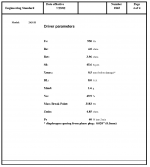
Without further ado, here's my 'guesstimate' for the Thiele Small parameters of the B&C DE25 compression driver. Note that you can use these specs to simulate other drivers too. At midrange frequencies the geometry of our devices have a much greater effect on frequency response than Thiele Small parameters. But we gotta plug SOMETHING into our software programs, otherwise our results will be completely random. I hope these specs are a good starting point. (They weren't easy to derive, believe me!)
Sd = 14.66 (note this isn't 22cm - I can post why that is if anyone's curious)
Cms = 1.80e-05
mmd = 3.08gm
Re = 6.3ohm
Bl = 18.00
Rms = 1.0
Le = 0.11
Fs = 672hz
Qes = 0.26
Qms = 13.15
Vas = 0.01
Qts = 0.25
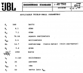
For comparison, here's the numbers that John Hasquin published:
Sd = 15
Cms = 2.00e-05
mmd = 1.0gm
Re = 6.3ohm
Bl = 7.5
Rms = 1.0
Le = 0.025ohm
Fs = 1110hz
Qes = 0.80
Qms = 7.18
Vas = 0.01
Qts = 0.72
The above is quoted from Audio Psychosis • View topic - Simulating a B&C DE25
There are only two things I don't agree with in Patrick Bateman's (John) DE25 parameters. I've actually measured the Sd of a DE25 diapgragm and know it is 18.09557cm^2. The second thing is there is no way BL can be 18 T*m. It has to be somewhere between 7 T*m and 9 T*m. I do agree that Patrick's numbers for Fs, Qes, and Mmd are probably better than mine - Hey this was early on and we've learned so much since then.
- Status
- This old topic is closed. If you want to reopen this topic, contact a moderator using the "Report Post" button.
- Home
- Loudspeakers
- Multi-Way
- Modelling compression drivers