I am working with some of the cheap KSN1025 knock-offs from parts Express, the GT-1025 3x7 Piezo Horn Mid-Tweeter. I thought this would interesting to try in a 2-way speaker with a cheap 4" woofer, also a Goldwood, that I got some time ago from All Electronics. This piezo can go as low as 2K so there is a lot of range in the combination for what cross-over point to use. The idea of this little project is to see how good a speaker I can make with these cheap drivers. One of the things I like about using a piezo tweeter here, besides it's being probably the cheapest tweeter out there, is the fast transient response and ability to go well above the human hearing range. My son is learning to play the flute and I have noticed that when he plays the flute our dog howls even if she is in another room. But, we can listen to flute music on the stereo and the dog could care less even if she is curled up 3 feet from a speaker. Obviously the stereo is not reproducing the full sound of this instrument. In fact, up close and personal the flute has a lot of sibilance and even harshness, the same sorts of things which are often points of complaint against piezo tweeters. Maybe this aspect of piezo's isn't an entirely bad thing.
Of course, when you are reproducing a pure sine wave tone, then you do not want to hear sibilance or harshness, and I do hear those characteristics if I just hook the GT1025 up to an amp directly with no cross-over components and play a sine wave tone generated on the computer through it. So, I wanted to experiment with this unit to see if I could make it sound more civilized, and that brings me to the question in the subject line -
After searching the forums here for information I found the recommendations to coat the paper cone with damar and to put some wadding in the space behind the cone and piezo transducer. I did not have damar so I used thinned Modge Podge (MP) on the paper cone. BTW, the Modge Podge treatment did wonders for the midrange of those close-out 4" GW woofers. I can raise the cross-over point now if I want to. Anyway, the MP coating did indeed improve the purity of the sound of the sine wave tone from the tweeter, and placing a pinch of polyester stuffing behind the transducer seems to have smoothed out the early peak in the 2-3k range some.
What I don't understand is how this piezo driver works, now that I have seen it's indisdes. The piezo sandwich is glued to the apex of the paper cone, and the rim of the cone is held pinched between two layers of the plastic housing when the screws are tightened down. But that leaves the piezo sandwich dangling in space back there behind the cone. What gives with that? Wouldn't placing something behind it, like the fiber pad, probably press it against the point of the horn which the round rear case sections are screwed onto? You can press against the piezo disk sandwich from behind when you have taken the rear cover off and it does not move forward, so apparently that is how it is supposed to be. But, if the apex of the paper cone is fixed against that point behind the horn throat, how is the paper cone being vibrated? I can't quite picture how this works.
Datinker
Carl asked:
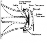
Are there no dampers as shown here?
Attachment: picture 1.png
(cutaway drawing of a similar piezo horn with a foam dampener in fron of the bimorph and a rubber dampener behind it)
This GT1025 unit has neither the foam in front or the rubber behind the bimorph. That is why I don't get it. The diagram you supplied must be of one of the more high-class units from Motorola. Even so, in your diagram I still don't see where either dampener or anything other than the rim of the cone is anchored to anything solid. Maybe these things shake the cone simply against the suspended mass of the bimorph?
The unit I took apart and put the MP coating on is a spare just sitting naked on the desk. The ones which are mounted in the 2-way speaker boxes have a 22ohm parallel and 40 ohm series resistor, and this combo is crossed over to the woofer with an AR-SXO cross-over. The electrical components alone already have it sounding much nicer than the bare unit on the desk, but I think I can do better still after these experiments.
I didn't think that this cross-over would work after all the warnings I have read about using an inductor with a piezo, but this sounds pretty good. Much better than just a capacitor for the piezo and an inductor for woofer. The mounted piezos have some modelling clay on the backs of the plastic horns to damp the hollow plastic resonance, but no other mods yet. The plastic sounds nice and dead when I tap it now.
I am interested in trying an ENAbl pattern on the cone but I am unsure about where to put the pattern if I don't know how the moving parts are actually moving.
Datinker
Datinker said:Carl asked:
Cal asked
Attachment: picture 1.png
(cutaway drawing of a similar piezo horn with a foam dampener in fron of the bimorph and a rubber dampener behind it)[/B]
No seeum pic
This GT1025 unit has neither the foam in front or the rubber behind the bimorph. That is why I don't get it. The diagram you supplied must be of one of the more high-class units from Motorola. Even so, in your diagram I still don't see where either dampener or anything other than the rim of the cone is anchored to anything solid. Maybe these things shake the cone simply against the suspended mass of the bimorph? [/B]
The foam damper, in part, prevents the element from "rocking" back and forth and to tame the ringing. It doesn't need much more as the element is very light, glued to the diaphragm in the center and held in place at the flare by the cap. It doesn't move in the same way as a dynamic driver does, the element kind of slides back and forth across itself when excited and transfers that movement to the diaphragm. The one on the back of the element I am guessing is a form of stabilizer and acoustic damper.
I didn't think that this cross-over would work after all the warnings I have read about using an inductor with a piezo, but this sounds pretty good. [/B]
I am definitely not the one to talk to about piezos. I've been known to do some rather off the wall things with piezos and inductors and I can still hear people shaking their heads wondering what Cal's up to next.
I am interested in trying an ENAbl pattern on the cone but I am unsure about where to put the pattern if I don't know how the moving parts are actually moving.[/B]
Talk to BudP and planet10 among others about those things.
Most piezo horns have a sharp peak in the 2KHz range and then a deep dip in the 3-4KHz range before becoming more linear above about 5KHz. Generally it's that initial range peak that account for most of the bad qualities in a piezo horn, so generally they should just be used over 5KHz.
Luckily that's an easy fix. Just add a series resistor. That will work a highpass filter in itself and at the same time make the piezo a reasonable load for the amp since a piezo is a capacative load the equation is exactly the same as for a normal 1st order highpass but instead of calculating the capacitor, you calculate the resistor value you need.
R = 0.159 /(C*f)
R = resistor value in Ohms
C = piezo's capacitance in Farads
f = desired x-over frequency in Hertz (a good starting point is 3.5KHz)
Bear with me here, as I have not figured out how to get text of a previous post quoted in my reply.
Cal, sorry about calling you Carl in my first reply!
The picture I referred to was the one you had attached to your first post in this thread.
You said the foam keeps the bimorph from rocking back and forth. OK, I can believe that. Seems like it should be easy to add a similar foam ring to one of these units. Could be something to try.
Further, you said that the bimorph element slides back and forth across itself in the side to side direction. I would have thought it expanded and contracted in thickness between the two electric poles since the contacts appear to be the front and back faces of the disk. But if the motion was occurring on that axis then letting the center of the diaphragm rest against a hard point wouldn't make sense. To me, at least. So you may be right about a more side-to-side motion.
Another possibility is that the disk warps in response to the applied electric field. Again, we would need to know in which direction it warps to make sense of this device.
If planet10 doesn't show up here, in which forum should I post a question about this?
http://www.planet10-hifi.com/piezo-XO.html
I'm not sure how the crystal actually moves in response to an electrical signal, but i expect that warp is the most likely.
Mod Podge was a much better call than damar IMO. EnABLing these would be interesting.
dave
I'm not sure how the crystal actually moves in response to an electrical signal, but i expect that warp is the most likely.
Mod Podge was a much better call than damar IMO. EnABLing these would be interesting.
dave
bi morph material flex to the electrical charge
the materical arches with the change of voltage so fast and with such effiecency that it achieves too good frequency response and spl. That is why most people do not like them for they will bring out the crosstalk distortion and the noise in the signal that can be introduced by crossover and other noises so clearly and trying to adjust it to personal taste in a room can be a pain, they are best suited for outside where the extra dbs needed to be easily pushed with less load since the bass will need 2 to the n for each 3db increases
the materical arches with the change of voltage so fast and with such effiecency that it achieves too good frequency response and spl. That is why most people do not like them for they will bring out the crosstalk distortion and the noise in the signal that can be introduced by crossover and other noises so clearly and trying to adjust it to personal taste in a room can be a pain, they are best suited for outside where the extra dbs needed to be easily pushed with less load since the bass will need 2 to the n for each 3db increases
i had an idea for a effecient piezo indoor tweeter
a gas charge chamber the is double the atmosphere with a soft elastic membrane that is connect to one that is a little less that atmosphere pressure that forms a dome. The extra pressure on the vibrating diaphram would hopefully cut the dbs down to where it would not be so intense the lack of total atmospheric pressure would hopefully eliminate the sensitivity to the inherent noise of the electronic be sensed and projected. Plus hopefully the membrane vibrating in all direction would have a good dispersion characteristics.
a gas charge chamber the is double the atmosphere with a soft elastic membrane that is connect to one that is a little less that atmosphere pressure that forms a dome. The extra pressure on the vibrating diaphram would hopefully cut the dbs down to where it would not be so intense the lack of total atmospheric pressure would hopefully eliminate the sensitivity to the inherent noise of the electronic be sensed and projected. Plus hopefully the membrane vibrating in all direction would have a good dispersion characteristics.
Re: bi morph material flex to the electrical charge
What is Xmax on a typical piezo....
mcmahon48 said:the materical arches with the change of voltage so fast and with such effiecency that it achieves too good frequency response and spl. That is why most people do not like them for they will bring out the crosstalk distortion and the noise in the signal that can be introduced by crossover and other noises so clearly and trying to adjust it to personal taste in a room can be a pain, they are best suited for outside where the extra dbs needed to be easily pushed with less load since the bass will need 2 to the n for each 3db increases
What is Xmax on a typical piezo....
Re: Re: bi morph material flex to the electrical charge
Basically there is no Xmax on a piezo since it doesn't make sense to talk about as the cone material doesn't move back and forth as in a regular dynamic driver but flexes instead. You could talk about a maximum curvature before the crystal breaks down though.
On how the flex. Well, when applied with a voltage they warp to form a dome shape in one or the other direction depending on the polarity of the voltage. You can then either center mount it and use this warping much like a ring radiator or you can suspend it in a rubber suspension and use it much like a regular dome shaped driver.
electroaudio said:What is Xmax on a typical piezo....
Basically there is no Xmax on a piezo since it doesn't make sense to talk about as the cone material doesn't move back and forth as in a regular dynamic driver but flexes instead. You could talk about a maximum curvature before the crystal breaks down though.
On how the flex. Well, when applied with a voltage they warp to form a dome shape in one or the other direction depending on the polarity of the voltage. You can then either center mount it and use this warping much like a ring radiator or you can suspend it in a rubber suspension and use it much like a regular dome shaped driver.
planet10 said:
Hi Dave, you might want to update that piezo x-over file with my idea I posted above. It's a much more simple and better sounding x-over with piezos than trying to shoehorn a piezo to work as a regular driver.
Also remember that a series capacitor will attentunate the piezo just as a resistor attunates a relugar driver, so using a standard filter on a piezo, even after making it electriclly look like a regular driver, will have very detrimental effects on the sound.
Just try it. You'll be pleasantly surprised.
Datinker said:You said the foam keeps the bimorph from rocking back and forth. OK, I can believe that. Seems like it should be easy to add a similar foam ring to one of these units. Could be something to try.
I quoted your text by putting a check in the "quote" box, under your post before hitting reply.
I think it would be interesting to hear a comparison of different materials here. Especially if the 2khz behavior mentioned by Saturnus could be addressed. From Cal's initial pic it looks like there are two different materials used. This seems like a non-trivial amount of manufacturing effort, I expect there would have been a reason to implement it.
Saturnus said:you might want to update that piezo x-over file with my idea I posted above. It's a much more simple and better sounding x-over with piezos than trying to shoehorn a piezo to work as a regular driver.
Just try it. You'll be pleasantly surprised.
Write me up a little article and i'll add it... knowing what typical capacitances one is working with would be good.
I gave all my good piezos to Cal...
dave
panomaniac said:Good idea, Saturnus!
Thanks for posting that.
Thanks.

Forgot to mention that you must use ultra-low inductive film or carbon resistors as even "non-inductive" wirewound typically has to high inductance. It only takes a few hundred nH's to start it working as lowpass filter in the audible range.
Saturnus said:Forgot to mention that you must use ultra-low inductive film or carbon resistors as even "non-inductive" wirewound typically has to high inductance. It only takes a few hundred nH's to start it working as lowpass filter in the audible range.
Firstly ... typo ... uH, not nH
I should explain and illustrate this perhaps. Piezos have capacitances in the 0.1uF to 1uF range depending on size of the diaphram and manufacturer more than on cost per say. You can't say, low is good and high is bad, for instance, it doesn't work like that. Just as you can't say a 16 Ohm driver is better than a 4 Ohm one.
Now if we take my preferred one I used in the Boominator (see sig), that's a Zomax HP100. It's capacitance is 0.30uF
Put into the standard equation, just replacing Z with C gives a 151Ohm resistor if the desired x-over frequency is 3.5KHz.
Since we want almost no phase shift and attunation in the audible range we say that the lowpass x-over frequency automatically induced by the series resistor must be at least 80KHz (2 octave above the audible range). Now take this into the standard equation:
L = R / (6.28*f)
And we see that the series inductance of the resistor used should be less than 300uH.
Re: Re: Re: bi morph material flex to the electrical charge
I am familiar with bimetallswitches, piezos for servos and such stuff regardless of shape.
what i meant, are they linear att all or how small is the linear movement...
Saturnus said:
Basically there is no Xmax on a piezo since it doesn't make sense to talk about as the cone material doesn't move back and forth as in a regular dynamic driver but flexes instead. You could talk about a maximum curvature before the crystal breaks down though.
On how the flex. Well, when applied with a voltage they warp to form a dome shape in one or the other direction depending on the polarity of the voltage. You can then either center mount it and use this warping much like a ring radiator or you can suspend it in a rubber suspension and use it much like a regular dome shaped driver.
I am familiar with bimetallswitches, piezos for servos and such stuff regardless of shape.
what i meant, are they linear att all or how small is the linear movement...
Re: bi morph material flex to the electrical charge
I will try to use the quote feature here. Thanks to Adam for pointing out how this works.
Mcmahon48,
I searched around using Google and Wikipedia for general information on piezo bimorphs last night and found the same information. The disk goes convex/concave in response to voltage and polarity of the applied electric field.
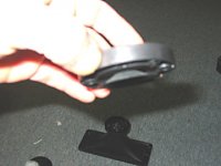
So, now we know what the motion of the biomorph transducer is. All I/we need to complete the picture is knowing how that motion is transferred to the diaphragm. I took some pictures of the unit as I was taking it apart and made these 6 figures to refer to.
Fig1 is the whole GW-1025 piezo unit.
Fig2 show the back side of the back of the bimorph disk which you see when you remove the top cover or lid. Note the break in the inner rim inside the lid which makes the rear chamber a little larger. You can see this in the next figure as well.
Fig3 shows the center ring containing the bimorph, diaphragm, and terminals, can be removed as a section. There are two alignment pins on it so that the lid can only go on one way. Presumably prevents one from confusing which terminal is plus and which is minus, since those markings are on the lid.
Fig4 shows the horn in profile so you can see the cone shaped section that the diaphragm fits over. It fits very close together with the diaphragm. This is why I raised the question about how the diaphragm can be vibrated by the bimorph if it is touch the tip of the cone right in the center where the diaphragm is glued to the bimorph disk.
Fig5 shows that if I push on the bimorph from behind the assembly of bimorph and diaphragm can be pushed up out of the ring section as far as the wires will allow. The disk is hanging free in space other than for the one attachment in the center to the point of the diaphragm.
Fig6 shows that if you hold this assembly upside down it dangles freely on the wires.
I had a more critical look at this and I think that there is maybe a very small gap between the tip of the cone on the back of the horn and the center of the diaphragm when the center ring section is attached to the back of the horn and the rim of the diaphragm is gripped between the ring and the horn. It can't be a whole millimeter though. X-max has to be small, at least for the diaphragm. Remember that the disk is not pushing against the diaphragm from a solid point so it could move a lot more than the thickness of this gap.
I have to wonder why, if this description of how this unit is put together is correct, the center of the diaphragm would not buzz against the tip of the cone sometimes.
And I have to conclude that the diaphragm is only vibrated against the counterbalancing mass of the freely suspended disk. Given these two conclusions I have to wonder how good an idea it is to put much stuff behind the disk at the risk of forcing contact between the diaphragm and cone tip.
Makes me wonder is shaving a bit of the cone tip and putting a tiny dollop of silicone on there might not be a good idea. Should prevent buzzing at high diaphragm excursions.
The foam ring in the diagram Cal supplied does look like a good idea, depending on whether the diaphragm material needed extra damping. And in that model piezo horn I could see the rubber damper acting as a rear surface for the disk to push off from. A surface that is itself compliant and whose relative stiffness and dampness would have a large effect on the sound quality. That seems like something a tinkerer could try to add to this unit. Since that would be going from the current state of affairs where the disk is pushing off against nothing to one where the disk is pushing off against something, this rubber would have to be pretty light material to avoid overdoing it and forcing the diaphragm to hit the cone.
I will try to use the quote feature here. Thanks to Adam for pointing out how this works.
mcmahon48 said:the materical arches with the change of voltage so fast and with such effiecency that it achieves too good frequency response and spl. That is why most people do not like them for they will bring out the crosstalk distortion and the noise in the signal that can be introduced by crossover and other noises so clearly and trying to adjust it to personal taste in a room can be a pain, they are best suited for outside where the extra dbs needed to be easily pushed with less load since the bass will need 2 to the n for each 3db increases
Mcmahon48,
I searched around using Google and Wikipedia for general information on piezo bimorphs last night and found the same information. The disk goes convex/concave in response to voltage and polarity of the applied electric field.
So, now we know what the motion of the biomorph transducer is. All I/we need to complete the picture is knowing how that motion is transferred to the diaphragm. I took some pictures of the unit as I was taking it apart and made these 6 figures to refer to.
Fig1 is the whole GW-1025 piezo unit.
Fig2 show the back side of the back of the bimorph disk which you see when you remove the top cover or lid. Note the break in the inner rim inside the lid which makes the rear chamber a little larger. You can see this in the next figure as well.
Fig3 shows the center ring containing the bimorph, diaphragm, and terminals, can be removed as a section. There are two alignment pins on it so that the lid can only go on one way. Presumably prevents one from confusing which terminal is plus and which is minus, since those markings are on the lid.
Fig4 shows the horn in profile so you can see the cone shaped section that the diaphragm fits over. It fits very close together with the diaphragm. This is why I raised the question about how the diaphragm can be vibrated by the bimorph if it is touch the tip of the cone right in the center where the diaphragm is glued to the bimorph disk.
Fig5 shows that if I push on the bimorph from behind the assembly of bimorph and diaphragm can be pushed up out of the ring section as far as the wires will allow. The disk is hanging free in space other than for the one attachment in the center to the point of the diaphragm.
Fig6 shows that if you hold this assembly upside down it dangles freely on the wires.
I had a more critical look at this and I think that there is maybe a very small gap between the tip of the cone on the back of the horn and the center of the diaphragm when the center ring section is attached to the back of the horn and the rim of the diaphragm is gripped between the ring and the horn. It can't be a whole millimeter though. X-max has to be small, at least for the diaphragm. Remember that the disk is not pushing against the diaphragm from a solid point so it could move a lot more than the thickness of this gap.
I have to wonder why, if this description of how this unit is put together is correct, the center of the diaphragm would not buzz against the tip of the cone sometimes.
And I have to conclude that the diaphragm is only vibrated against the counterbalancing mass of the freely suspended disk. Given these two conclusions I have to wonder how good an idea it is to put much stuff behind the disk at the risk of forcing contact between the diaphragm and cone tip.
Makes me wonder is shaving a bit of the cone tip and putting a tiny dollop of silicone on there might not be a good idea. Should prevent buzzing at high diaphragm excursions.
The foam ring in the diagram Cal supplied does look like a good idea, depending on whether the diaphragm material needed extra damping. And in that model piezo horn I could see the rubber damper acting as a rear surface for the disk to push off from. A surface that is itself compliant and whose relative stiffness and dampness would have a large effect on the sound quality. That seems like something a tinkerer could try to add to this unit. Since that would be going from the current state of affairs where the disk is pushing off against nothing to one where the disk is pushing off against something, this rubber would have to be pretty light material to avoid overdoing it and forcing the diaphragm to hit the cone.
Attachments
- Status
- This old topic is closed. If you want to reopen this topic, contact a moderator using the "Report Post" button.
- Home
- Loudspeakers
- Multi-Way
- How do these piezo tweeters work?