You have to be careful
don,t tweek the disk and also the dampening device has to be correctly cut for it will affect the frequency range by how much you restrict the disk
they have to have a certain amount of room to freely move I would suggest to go to ebay and find some D25NC-55-06 DOME TWEETERS! for there have been a bunch suddenly out there and they are a very good deal I bought some
As to the underlying piezo principle in the speaker operation, this is very similar to the 'electronic' igniters you see in butane lighters and other places.
In this case, you flex a ceramic crystal, and it produces electricity, as in an igniter spark.
But they work exactly the opposite as well. Instead of flexing the crystal to produce electricity, you apply electricity and it flexes the crystal. Flex it fast enough, and connect the crystal to a diaphragm, and sound comes out.
I think that is the underlying principle in a nutshell.
Steve/bluewizard
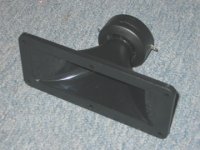
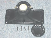
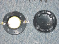
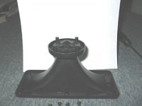
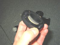
All I/we need to complete the picture is knowing how that motion is transferred to the diaphragm. I took some pictures of the unit as I was taking it apart and made these 6 figures to refer to.
It is actually the disc's inertia that is responible for mechanically coupling (maybe "grounding" would be a good expression) the bending motion to the diaphragm.
This is building some sort of mechanical highpass and therefore it is possible (though not advisible in the interest of good sound) to use this drivers without an electrical crossover.
The second mechanical highpass in this tweeters is the horn of course.
Regards
Charles
phase_accurate said:
It is actually the disc's inertia that is responible for mechanically coupling (maybe "grounding" would be a good expression) the bending motion to the diaphragm.
This is building some sort of mechanical highpass and therefore it is possible (though not advisible in the interest of good sound) to use this drivers without an electrical crossover.
The second mechanical highpass in this tweeters is the horn of course.
Regards
Charles
Yes, it appears to be simply the disk's inertia that works against the diaphragm. In fact I found that you get the same level of sound out of the horn by simply rubbing your finger about on the back of the bimorph disk. So, I do not think the diaphragm really moves in and out at all. Rather it just vibrates like a tin can does with a tuning fork placed against it. Which would mean that the timbre of the sound would greatly depend on the material the diaphragm is made of. And it would explain why this device can work with such a small gap between the diaphragm and the cone on the back of the horn.
As for what this means for the DIY tweaker, I would say that mods to the stiffness and dampness of the diaphragm material itself would pay off the most. And probably mods intended to reduce reflected sound from the rear chamber would be worthwhile. The ENAbl patterning still seems applicable as well. Anything that touches the disk to try and control or damp larger motions would have to be done with great care to avoid adverse effects on sound quality. Something light and rubber which touches only the rim of the disk might make sense to try, but it would have to be mounted in a "neutral" fashion. Meaning it should not press the disk in either direction, forward or backward. It would have to allow the disk center to vibrate freely while a signal is applied but help kill the vibration quickly when the signal ends.
Oh, thanks mcmahon48 for the tip about the D25NC-55-06 domes on E-Bay. I will have a look at that.
how do piezo's work
Hi Saturnus
I am interested on how i can figure out the capacitens
of 8 piezo's wired 2rows of 4 in paralell and then those two rows in series.Will one resistor controll them all,or do I need a resistor on each piezo;s? Using Goldwood
GT-1025 for my project.
Thanks in advance.
Maduras
Hi Saturnus
I am interested on how i can figure out the capacitens
of 8 piezo's wired 2rows of 4 in paralell and then those two rows in series.Will one resistor controll them all,or do I need a resistor on each piezo;s? Using Goldwood
GT-1025 for my project.
Thanks in advance.
Maduras
Just measure them electrically and use them in calculations like they were normal capacitors. Though not entirely true they are for all intent and purposes far more a pure capacitive load than a dynamic speaker driver is a purely resistive load.
So if you have capacitors in parallel the total capacitance is just the sum of these.
And when you have capacitors in series the total capacitance is the product of these divided with the sum.
So if one capacitors capacitance is equal to x then 8 of these with 2 series connected sets of 4 parallelled capacitors is equal to:
(x+x+x+x)*(x+x+x+x) / (x+x+x+x)+(x+x+x+x) <=> 4x*4x / 4x+4x <=> 16x / 8x <=> 2x
In any case it doesn't matter if you use one or many resistors as long as the total resistance is the same and the maximum self-inductance is observed.
Trial piezo modification results
First off I want to tell you all about a great thing I found to listen to on your tweeters for comparison purposes, or just for fun. In iTunes Radio is a folder called Ambient. In there is a channel called Birdsong Radio. They just play recordings of birds, and even though they are MP3s they sound really good. I love listening to this stuff on the piezo horns!
I have now tried several things to see what might help the sound quality or frequency response of these piezos.
First off, the diaphragm was given two light coats of Modge Podge and allowed to dry O/N. That already makes a noticeable improvement in the sound, as I mentioned earlier.
I tried mounting a rubber washer cut to just overlap with the outer 1mm rim of the bimorph disk, with the outer edge laying on the back of the plastic ring the bimorph sits it. The back of the disk and the back of the plastic ring section are even so this rubber ring sits flat, in a neutral position.
This definitely damped down the early peak around 2500 Hz, and the piezo did sound a little more clear, but it also damped down the sound over the rest of the range. I tried cutting off most of the outer section of the rubber ring so that it was just touching the plastic ring section in four short segments each about 4 mm long. That did not seem to make much difference in the degree to which this damped down the overall sound level.
However, I found that you can put 4 small pieces of thick felt between the outer edge of the rim and the ID of the plastic ring section that houses the bimorph disk without killing the sound level. It is harder to tell if this has any really positive effect without a lot of critical listening comparisons I don't want to take the time for just now, but I will keep the keep the felt in there. It should at least help to kill some back reflections.
I also tried putting an ENAbl pattern on the front of the diaphragm, one ring at the outer circumference and one down next to the apex, with a dot in the center of the little flat spot where the diaphragm connects to the disk. The pattern was rather poorly made (it is such a tight space to work in) with flat black artist acrylic and coated with Micro Gloss. The paint had to be diluted by half and even then it doesn't really flow in the speedball nib.
This mod makes a noticeable improvement in the clarity of the sound even at high volume levels. I _really_ like listening to the birds now. This is a keeper! As soon as I heard it I treated the other one. I assembled the unit with the felt pads around the bimorph rim, lined the rear chamber with felt, and placed a pinch of poly batting in the rear chamber. That is how I will use this piezo tweeter. It sounds very good now, but it still has the peak around 2500 Hz. The recommendation to cross this unit over at 3500 Hz will still apply.
Now I'll see if these can make the dog howl if we play flute music...
Datinker,
How large are your piezos?
I have a pair of Motorolas that have been waiting for a tinkering session now for a few years, but they are larger than what I had seen in the past. Probably 3-4" diameter housing for the diaphragm with 1-1/8" throat, and if memory serves, the specs said to treat them as an 8uF cap for calculations.
Curious to hear more listening impressions/comparisons...
And thanks for the discussion everyone, maybe it's time to play with them a bit.
piezo's
Hi Tim
Does this unit have a threaded end?If so then this is one of the better units Motorola made.With the proper horn screwed on this thing will go down to 1000Hz
Handels 400 watt's and 99 db 1w/1m.
Had them in a PA system 30 years ago.What I learned then was that you need the unit removed from the bass enclosure.Mine was a two way twelf inch.
If you play the bass unit and disconnect the piezo and hook it up to a scope you can see that it is creating a nice voltage.It was because of the cheap plastic housing that was activated by the pressure inside the box
After removing the unit from the box and mouting it on top of the box the sound was much improved.Might make no diffirents for what I am trying to do now,as it will be for domestic use so High SPL not required.
Don't have the units anymore so playing now with cheap china knock-offs.
Cheers
Maduras
tsmith1315 said:... the specs said to treat them as an 8uF cap for calculations.
That seems a bit high. Might your memory serve you incorrectly and it's 0.8uF instead?
In any case, just measure them, that'll give the correct value for sure.
Either way, I find tinkering with these things intriguing. It only takes a little simple modding (dampening the diaphram, housing and horn) and treating them correctly electrically for them to sound relative good compared to similarly effecient drivers of much higher price.
Saturnus said:
That seems a bit high. Might your memory serve you incorrectly and it's 0.8uF instead?
Exactly. I just dug them out of the shop and my memory is a decade off. In more ways than one...
Maduras:
Does this unit have a threaded end?If so then this is one of the better units Motorola made.With the proper horn screwed on this thing will go down to 1000Hz
Yep, it's threaded. And oddly enough the box proclaims 400W power handling, just as you stated.
Maybe they'll end up as a reasonable complement to a very small HT setup to come.
piezo
Hi Tim
The horn that I had on that piezo was a EV horn.No longer made ofcourse.But is was the only horn that would get this piezo down to 800Hz.Others will work but none as low.Nice thing is the standert thread used in the Pro world,so you can mound any horn on it.
I too want this to work for a HT,but as array.Using the dual element one from MCM.So far, with no mods eight in a array sound one hell of a lot better than a single unit
Cheers
Maduras.
- Status
- This old topic is closed. If you want to reopen this topic, contact a moderator using the "Report Post" button.
- Home
- Loudspeakers
- Multi-Way
- How do these piezo tweeters work?