Hi again.
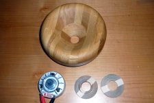
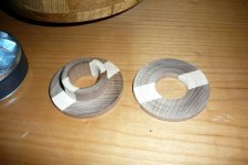
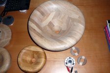
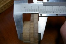
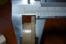
Now I´ve made two different spacers and measured both.
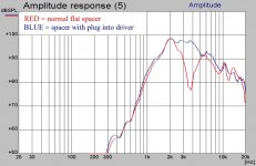
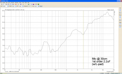
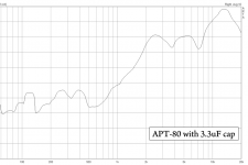
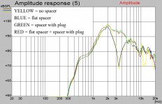
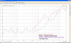
As you can see the spacer with the plug into the driver make a huge difference.
The mic was placed 30cm from the horn mouth and the signal was gated, no smoothing was used.
That little driver actually measures pretty good on a waveguide.
Can you post a link to where you found the foam ?
Now I´ve made two different spacers and measured both.
As you can see the spacer with the plug into the driver make a huge difference.
The mic was placed 30cm from the horn mouth and the signal was gated, no smoothing was used.
That little driver actually measures pretty good on a waveguide.
Can you post a link to where you found the foam ?
Attachments
Kim has overtaken me
There is indeed a cavity inside.
I drew some rough sketches (just about when you discussed the above):
The first is the ATP-50 with APT-3 adaptor, like I said it's straight:
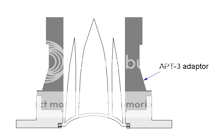
I don't think there's any proper horn with a throat that is perfectly straight. There should be at least a little angle at the starting point. So with this adaptor, there's inevitably dffraction happening here - the transition of straight/angled wall. What a bad and irresponsible design!
But there's catch. Look carefully, there's a tiny step at the edge of outer slot. APT-3 (and APT-80 horn) has that proper little rim to fill that step properly and make the passage perfectly smooth.
I think this is critical. As the very high frequency sound is mostly comming from the outer edge and surround of the dome, i.e., the outer slot of the phase plug. So anything unsmooth here is not welcome.
The second, Simon this is what you do (I suppose):
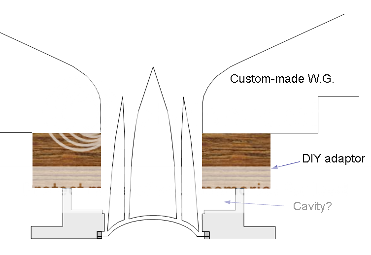
Please don't overlook anything (big or small) near the throat. Everything is critical near here. Anything breaks the continuity is not good.
In addition, I hate to say that, but, Simon your WG looks not smooth to me (or have I already mentioned that?).
The contour of an OS waveguide is based on an assumption that the waveform at the throat is flat. At this APT tweeter, I can't point out where the wave is flat Maybe it's never flat
I'm not sure it's the shooting angle or what, it seems the expansion at your throat of WG is quite 'sudden'. To my eyes, it's almost a right angle with slightly rounded edge. It's different from other OS WG's I've seen around here.
And back to the 'starting point' of the WG, I think it's worth further discussion....
The following is what Kim mentioned, APT-80 horn:
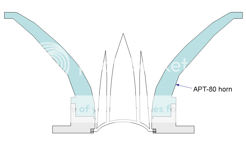
As you can see (or better yet, your own ones), the flare starts very early, near the base of phase plug. I think, the shape of the phase plug and the contour of this horn must be considered together. Or, they should be.
Ironically, this is quite different from the very first drawing with APT-3 adaptor. I can't tell which is correct. (Or they're both wrong? )
I myself use Dayton's WG, which needs that lousy straight PT-3 adaptor to assmebled properly. However the throat of Dayton's WG is 29mm I.D. instead of standard 1" (25.4mm), so there's a 2mm step at where they joint. This happened to give me a chance to flare out the APT-3 a little, so this is what I do:
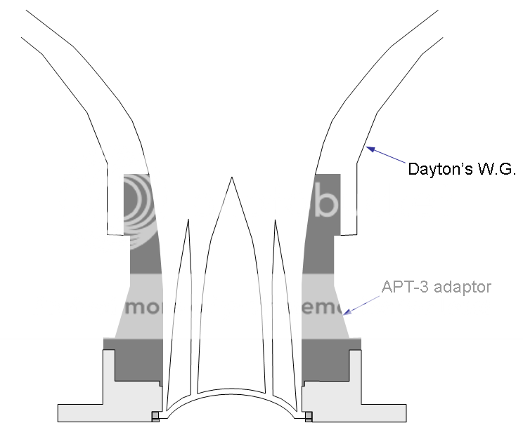
And luckily it's plastic and quite easy to file and sand to make them smooth (well, as much as I can).
Again, I still don't know exactly which is correct (or none of them is). Waveform can't be seen and I can't measure, either
To my ears, APT-80 is smooth, straight or stepped throat of APT-3 is not (and very audible), modded and flared APT-3 with Dayton is smooth again. So, at least it's worth the effort, to me.
For your reference.
There is indeed a cavity inside.
I drew some rough sketches (just about when you discussed the above):
The first is the ATP-50 with APT-3 adaptor, like I said it's straight:
I don't think there's any proper horn with a throat that is perfectly straight. There should be at least a little angle at the starting point. So with this adaptor, there's inevitably dffraction happening here - the transition of straight/angled wall. What a bad and irresponsible design!
But there's catch. Look carefully, there's a tiny step at the edge of outer slot. APT-3 (and APT-80 horn) has that proper little rim to fill that step properly and make the passage perfectly smooth.
I think this is critical. As the very high frequency sound is mostly comming from the outer edge and surround of the dome, i.e., the outer slot of the phase plug. So anything unsmooth here is not welcome.
The second, Simon this is what you do (I suppose):
Please don't overlook anything (big or small) near the throat. Everything is critical near here. Anything breaks the continuity is not good.
In addition, I hate to say that, but, Simon your WG looks not smooth to me (or have I already mentioned that?).
The contour of an OS waveguide is based on an assumption that the waveform at the throat is flat. At this APT tweeter, I can't point out where the wave is flat
Maybe it's never flatI'm not sure it's the shooting angle or what, it seems the expansion at your throat of WG is quite 'sudden'. To my eyes, it's almost a right angle with slightly rounded edge. It's different from other OS WG's I've seen around here.
And back to the 'starting point' of the WG, I think it's worth further discussion....
The following is what Kim mentioned, APT-80 horn:
As you can see (or better yet, your own ones), the flare starts very early, near the base of phase plug. I think, the shape of the phase plug and the contour of this horn must be considered together. Or, they should be.
Ironically, this is quite different from the very first drawing with APT-3 adaptor. I can't tell which is correct. (Or they're both wrong?
)I myself use Dayton's WG, which needs that lousy straight PT-3 adaptor to assmebled properly. However the throat of Dayton's WG is 29mm I.D. instead of standard 1" (25.4mm), so there's a 2mm step at where they joint. This happened to give me a chance to flare out the APT-3 a little, so this is what I do:
And luckily it's plastic and quite easy to file and sand to make them smooth (well, as much as I can).
Again, I still don't know exactly which is correct (or none of them is). Waveform can't be seen and I can't measure, either
To my ears, APT-80 is smooth, straight or stepped throat of APT-3 is not (and very audible), modded and flared APT-3 with Dayton is smooth again. So, at least it's worth the effort, to me.
For your reference.
CLS, the OS WG is nearly straight sided, it is only at the start of the throat it curves out, so it is hard to see in pictures. And if Simon´s WG is 45° then it looks very much like the expansion is quite sudden.
Geddes also mentioned that wood is not the best solution for OS WG´s as it is hard to make a perfect throat, but I think it looks so much better than the resin ones.
Those are some nice drawings, but your drawing of the APT-80 is not entirely correct, as the first about 15mm of the horn is straight, just as the APT-3.
I don´t think the straight sides matter much as long as the contour is set by the phaseplug, but it looks like the APT-3 adapter goes further out than the phaseplug.
The OS WG can be made to fit a driver with 0° at the throat.
Last edited:
...your drawing of the APT-80 is not entirely correct, as the first about 15mm of the horn is straight, just as the APT-3.
Yes, you are right.
I don´t think the straight sides matter much as long as the contour is set by the phaseplug....
I agree, to some extent. As I've mentioned, I think the overal expension should be set by the combination of phase plug and the surface around it, be it any adaptor or the throat passage of the driver itself. The APT seems a very special case in this regard.
APT-3 maybe make the passage too long and narrow, thus different loading to the driver.
However, in reality, this APT with straight adaptor sounds somewhat nasal to me. It smooths out and opens up quite a bit with the adaptor flared.
And I tried different Dayton's WG's, I like the bigger one which flares out faster (shorter and wider). It's less colored and more open.
Last edited:
I´ve also tried several horns and also turned two similar sized woodhorns, one with a tractrix contour and one with an OS WG 40° contour.
The OS WG sound so much better, it is more open and much less colored, but it´s also harder to make a crossover for it, as the tractrix loads the driver better.
I need to make some real adapters for the APT-50 drivers, so I can attach them firmly to the WG´s and get some listening done.
The OS WG sound so much better, it is more open and much less colored, but it´s also harder to make a crossover for it, as the tractrix loads the driver better.
I need to make some real adapters for the APT-50 drivers, so I can attach them firmly to the WG´s and get some listening done.
Chaps, this is wonderful stuff, and I really appreciate the time you've taken to post about such things.
Firstly, I feel I do have a slight nasal colouration, as well as a slight grainy edge, coming from the APT-50, which is not seen in the axial frequency response curve.
Secondly, my waveguide is a careful (I would say damn close) copy of the designs produced by the Excel spreadsheet presented in the Geddes on Waveguides thread, believed to be a "proper" OS waveguide profile. The profile of this waveguide is indeed exactly straight in the middle. It is only the throat and mouth that have some "roundover" area, which only runs for a very short stretch. Maybe the photos are misleading.
Where my understanding of how best to implement this setup falls short is in knowing which part of the APT's phase plug should be level with the start of the throat. I think the B&C drivers (and others??) used by Geddes have a flatter phase plug section and apparently flatter wavefront, if my terminology is correct. I am trying to meld the APT into something that it is probably not 100% right for. Please do bear in mind, my longer term plan was to use a more esoteric tweeter later on, when funds permit.
All that said, I want to get a better result from this APT, so I am all ears. I will be investigating these steps and gaps. I must admit, I didn't realise that cavity off to the sides was of great consequence.
I still have my APT-80 mini-horns so I could do some chopping and re-working of those in order to gain a smoother transition into the waveguide, but I may need some guidance with regards to how far into the throat the phase plug's end should sit.
Many thanks,
Simon
Hi again.
Now I´ve made two different spacers and measured both.
As you can see the spacer with the plug into the driver make a huge difference.
Can you post a link to where you found the foam ?
Hi, your graph is most conclusive and interesting! Before I moved my tweeter back I had a bad response, but actually now it looks ok. I'd better take a fresh measurement with the driver in isolation.
Here's one place I saw the foam for sale: eFoam, all sorts of foam: Reticulated Aquatic Filter Foam
Regarding where the phaseplug should be in the throat, I measured the APT-80 horn to start at about 13-15mm.
I would make a rough cut on the APT-80 horn and then sand it down until you got a 1" hole fitting you waveguide perfectly.
The B&C driver has the phaseplug hidden in the exit throat, and so does the BMS 4524 drivers I have.
But I dont think the APT-50 will benefit of this unless the adapter has a slight angle to it, causing the waveguide throat to be larger than 1" inch.
Measuring with inside callipers how far the 1" section goes (APT-80 horn) I'd agree it's about 15mm in. I will cut away slightly further than this and file it back and try to match it perfectly to my waveguide.
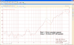
Here's one of my tweeters measured as-is, using the ~10mm wooden spacer with its probable issues. There's a fair old peak at 1.8Khz and a following null at 2.85Khz. Perhaps this is related to my dodgy throat.
Also attached, for comparison, is the APT-50 (not 80 as it says) in the waveguide before the spacer was introduced.
More to come later.
Attachments
I've had a disaster
I cut and filed to a depth of 16.5mm +-0.1, totally forgetting the plastic "spacer" would begin from further back than the wooden one. The result is a phase plug that protrudes at least 5mm out of the waveguide. A complete disaster. The result is even worse than with the wooden spacer.
I cut and filed to a depth of 16.5mm +-0.1, totally forgetting the plastic "spacer" would begin from further back than the wooden one. The result is a phase plug that protrudes at least 5mm out of the waveguide. A complete disaster. The result is even worse than with the wooden spacer.
Attachments
 I´m sorry you dropped one of the drivers.
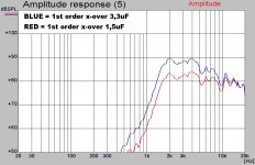
Something must not be right with your measurements, look at these I just made.
This time using the biggest WG I have to see if that makes a difference.
And as you can see my spacer with plug is also exaxtly 16,5mm, and the graph actually gets worse by adding the flat spacer.
Are you sure you had the gating set correct ?
Did you listen to it with the new adapter ?
I can hear a huge difference in the test noise between the flat spacer and the spacer with a plug. The one with the plug sounds more like white noise where the flat one sounds nasal.
Attachments
Last edited:
My measurements here are steady noise, they're not gated.
Your big waveguide looks like a salad bowl with a dressing drain hole... but it's amazing, like a work of art.
I think perhaps the hole on my spacer is smaller than on yours. It was basically 25mm on mine, perhaps a little less, say 24mm. I expect my measurements can be improved upon a lot but they're still relevant to one another as they're all done in a similar manner.
Notice most used 1/3 octave smoothing, but 1/6 octave on the last one I took.
I've cut my plastic down to the bare minimum now and glued it to my 10mm wooden spacer. I've then filed it down to be smooth internally and glued it to my waveguide, then added filler to build it up, ready for final shaping/sanding. We'll see what I can get then.
The phase plug is a little bit annoying to glue back in place and may mess up results a little more....
Simon
Hi,
I admire your dedication to helping and working these things out, it's really admirable.
See attached for the spreadsheet I used.
I've finished repairing, filling and sanding things on my waveguide so I'll solder and fix it back in place and measure it now. I'll take a picture too. After MUCH messing around I've got a good transition from waveguide to "tube" section, I think.
Attachments
ok, you use 60 degree angle for a total of 120 degree angle.
Why are you using 10 degrees for the throat angle ?
If I remember correctly the B&C driver you wanted to upgrade to is 6,5 degrees at the throat exit.
And the APT is at 0 degrees, but it might not matter when you have filed it smooth with the adpater you made.
BTW, how wide are your WG´s ?
Why are you using 10 degrees for the throat angle ?
If I remember correctly the B&C driver you wanted to upgrade to is 6,5 degrees at the throat exit.
And the APT is at 0 degrees, but it might not matter when you have filed it smooth with the adpater you made.
BTW, how wide are your WG´s ?
Last edited:
I'd say my throat angle is actually close to 0 degrees. I've taken a measurement of the new adapter set-up and it's looking rather different.
I'm sorry about the level mismatch between measurements and sub-optimally high xo point.
In spite of the issues raised I think I've at least managed to get a better curve, though it's still clearly a roller-coaster.
I'm sorry about the level mismatch between measurements and sub-optimally high xo point.
In spite of the issues raised I think I've at least managed to get a better curve, though it's still clearly a roller-coaster.
Attachments
- Status
- This old topic is closed. If you want to reopen this topic, contact a moderator using the "Report Post" button.
- Home
- Loudspeakers
- Multi-Way
- 3 way open baffle with Eminence and Skytronic