So the power to a driver is dependent on the impedence of the driver, and the impedence of the driver is dependent upon the frequency.
Instead of worrying about Zobel networks, perhaps I should think about pre-compensating, or performing some correction before amplification (in the spirit of active xovers and biamping). Perhaps in the feedback loop?
Intuitively, it would appear to be best to allow the amp to drive the driver directly where it has "stiffest" control over it.
walker said:I can take oscillograms but I still don't know how to post images, HELP?
Regards WALKER
if you email them to me i'll upload them to my site and email you back the exact stuff you'd need to paste into a post about them
(ie: (img)http://www.hakalugi.net/misc/walkerXXXXXX.jpg(/img) )
Won, you should not need to add any pre-emphasis unless the driver already has frequency response anomalies. The drivers should produce a flat response with their natural rising impedance, this is the natural order of things. Remember that as frequency rises the amount that the cone moves is reduced.
Hakalugi, I take it that I need to address the image in my posting and that I can't paste the image is this correct?
Regards WALKER
Hakalugi, I take it that I need to address the image in my posting and that I can't paste the image is this correct?
Regards WALKER
Hello,
I don't see much consensus here. Regarding the effects of keeping or not the Zobel network, in real-word active biamping,
I have a Pass XVR-1 to use initially for a 2-way biamp for a 4-way speaker. One amp just for two 15" woofers in each speaker and one amp output going to the passive 3-way XO in the speaker. I use four Krell fpb 750mcx monos, two for each channel.
The low pass passive XO circuit is one 6.8mH inductor making it a first order filter, but it also has a Zobel network in parallel to the drivers composed of 6x2R2 (in parallel, making a 0R37) followed by a 220uF cap. The cap and resistors of the Zobel are high quality Duelund.
Regarding driving the 15" drivers in this ative biamp configuration, I have two options:
a) Connect the amp directly to the drivers, removing both the inductor and the zobel network
b) Connect the amp to the drivers, leaving the zobel network.
I don't care about a reduction in damping factor in high frequencies because the 15" work mostly below 100hz.
What are your recommendations (besides trying both ways)?
Thanks
http://www.diyaudio.com/forums/multi-way/134632-biamping-crossovers.html
[/FONT][/COLOR]
The low pass passive XO circuit is one 6.8mH inductor making it a first order filter, but it also has a Zobel network in parallel to the drivers composed of 6x2R2 (in parallel, making a 0R37) followed by a 220uF cap.
This is actually not a Zobel as the resistance is well below the target DC resistance. This is a second order network with a small amount of corner damping (via the 0.37 ohm resistor.)
You must remove the complete network if you remove the inductor, otherwise the amp will be trying to drive 0.37 ohms at high frequencies.
A Zobel is not just a topology, if the values aren't such as to flatten impedance then it isn't a Zobel.
David
Current source amplifiers like First Watt F1 & F2 require flat impedance to have flat FR, so a zobel is necessary to adjust the high freq response.
Tube voltage amps have much higher output impedance than SS voltage amps so they respond more to the effects of a zobel. Low impedance SS amps don't care about impedance (within limit) so zobels are not often applied in commercial designs.
Tube voltage amps have much higher output impedance than SS voltage amps so they respond more to the effects of a zobel. Low impedance SS amps don't care about impedance (within limit) so zobels are not often applied in commercial designs.
Last edited:
Hi Won,
Perhaps my post below will shed some light.
http://www.diyaudio.com/forums/mult...sed-active-crossover-right-6.html#post4058118
Peter
Perhaps my post below will shed some light.
http://www.diyaudio.com/forums/mult...sed-active-crossover-right-6.html#post4058118
Peter
David,
The Pass XVR uses cascaded Sallen filters. So in order to have a 6db slope at a lower frequency and a steeper slope at a higher frequency, I have to use three poles. If I use two poles it behaves similarly to a two pole filter with a single frequency at the average. If I use three poles, the first with the lower frequency and poles 2 and 3 with the higher frequency, it behaves like a 6db filter for a lower frequency and a 18db for a higher frequency.
To get close to the original passive XO, removing the RC, I got to 66hz for Pole 1 and 320hz for Pole 2 and Pole 3.
So if in the passive XO the RC adds a second pole at a higher frequency, it seems I have two options:
1. Take out the series inductor and the parallel RC and use three poles in the active XO as discussed, but it becomes non-inverting (phase) at 18db whereas in the original passive XO the 12db is phase inverting, right?
2. Take out only the inductor, keep the RC and use only a 1st order in the active XO, leaving the second order portion for the parallel RC. In this case it could be more similar to the original and thus perhaps a better integration with the HP XO. I use Krell 750mcx monos, and the higher frequencies are already attenuated by the 6db filter, so I probably wouldn't worry too much about the low impendance at higher frequencies generated by the RC, right?
I wonder which of these two options is best.
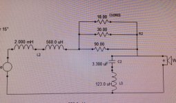
The band pass passive XO of the dual 8" woofers is a 2.56mH inductor in series with a 10R0 resistor. In parallel with the drivers is a 3.3uF cap in series with a 123.0uH Inductor.
Cheers,
VPN
The Pass XVR uses cascaded Sallen filters. So in order to have a 6db slope at a lower frequency and a steeper slope at a higher frequency, I have to use three poles. If I use two poles it behaves similarly to a two pole filter with a single frequency at the average. If I use three poles, the first with the lower frequency and poles 2 and 3 with the higher frequency, it behaves like a 6db filter for a lower frequency and a 18db for a higher frequency.
To get close to the original passive XO, removing the RC, I got to 66hz for Pole 1 and 320hz for Pole 2 and Pole 3.
So if in the passive XO the RC adds a second pole at a higher frequency, it seems I have two options:
1. Take out the series inductor and the parallel RC and use three poles in the active XO as discussed, but it becomes non-inverting (phase) at 18db whereas in the original passive XO the 12db is phase inverting, right?
2. Take out only the inductor, keep the RC and use only a 1st order in the active XO, leaving the second order portion for the parallel RC. In this case it could be more similar to the original and thus perhaps a better integration with the HP XO. I use Krell 750mcx monos, and the higher frequencies are already attenuated by the 6db filter, so I probably wouldn't worry too much about the low impendance at higher frequencies generated by the RC, right?
I wonder which of these two options is best.
The band pass passive XO of the dual 8" woofers is a 2.56mH inductor in series with a 10R0 resistor. In parallel with the drivers is a 3.3uF cap in series with a 123.0uH Inductor.
Cheers,
VPN
It depends on your viewpoint for the purpose of an amplifier output Zobel.
If one believes, or proves, that the amplifier requires an HF load to maintain the stability criteria, then no matter what load is on the other end of a set of cables, the Zobel must be fitted at the output devices and the local decoupling power ground.
If one believes, or proves, that the amplifier requires an HF load to maintain the stability criteria, then no matter what load is on the other end of a set of cables, the Zobel must be fitted at the output devices and the local decoupling power ground.
Unfortunately, your option 2 will not work and will potentially damage your amplifier.
I'm not totally following your description of the passive network you are replacing. By topology and value it is a 2nd order filter with a small series resistance in the shunt leg to modify the corner Q. This is a common technique that I often use. The L value needs to be high to pull the upper level down enough (often as part of a bass shelving or baffle step need) and the capacitor need to be a particular value to get the corner frequency right. That LC combination gives too much corner bump or Q so a resistor in the shunt leg lets you lower the corner Q. Others may look at it and say "Zobel!" but it isn't, as the value are not chosen to flatten impedance and do not flatten impedance.
You are describing it as a split pole in effect with a corner at 66 and a corner at 320. That doesn't make total sense to me but perhaps it is due to an interaction with the woofer impedance curve. This can often happen when large value low passes are brought in near the motional impedance bumps of the woofer.
Anyhow, the flaw in your logic is thinking that you can remove some elements in your network and lose some features of the low pass curve while retaining others. It just doesn't work that way. If you remove the input leg, the large L, then the RC remaining will not be a filter at all, rather it will be a high frequency short across the amplifier.
The problem is that the amplifier and it low output impedance will be driving the partial circuit and load. The amp will do its best to maintain constant voltage so no crossover action will happen at all.
You must remove the full circuit and then do your best to get back to the filter required with and active approach. Note that since there is probably a lot of interaction between the current network and the woofer impedance that you may actually be able to achieve better results with an active circuit that departs from your current network response.
Good Luck,
David
Hello,
As a follow up to my last question, as stated, I am using a PASS XVR-1 active crossover to drive two pairs of Krell FPB-750mcx. As per the recommendation here, a pair of monos driving directly the pair of 15" drivers in each each speaker, and the other pair driving the passive 3-way XO for the other drivers.
The speakers are four-way, with two 15", two 8", two 5" and one tweeter. I am keeping the passive portion for the bass/mid/highs
The passive pass-band for the 8" is a 2.56mH inductor (L1) in series with a 10R0 resistor (R1) plus Parallel to the two 8" drivers there is a 3.3uF cap (C1) followed by a 123.0uH inductor (L2)
Should I:
a- Keep the full pass-band of the 8" drivers and just use a lower frequency high pass in the Pass XVR-1 to feed it?
b- Take out the High pass portion of the band-pass of the 8" driver.
Which items of the band-pass should I take out or keep? Take out L1, R1, C1, and keep L2?
Thanks
VPN
As a follow up to my last question, as stated, I am using a PASS XVR-1 active crossover to drive two pairs of Krell FPB-750mcx. As per the recommendation here, a pair of monos driving directly the pair of 15" drivers in each each speaker, and the other pair driving the passive 3-way XO for the other drivers.
The speakers are four-way, with two 15", two 8", two 5" and one tweeter. I am keeping the passive portion for the bass/mid/highs
Should I:
a- Keep the full pass-band of the 8" drivers and just use a lower frequency high pass in the Pass XVR-1 to feed it?
b- Take out the High pass portion of the band-pass of the 8" driver.
Which items of the band-pass should I take out or keep? Take out L1, R1, C1, and keep L2?
Thanks
VPN
Keep the high pass for the Treble.
Keep the band pass for the 5"
Keep the low pass for the 8"
Use the active high pass filter as the high pass for the whole set of T+5"+8"
Use the active low pass filter to drive the 15"
One final check.
Will removing the high pass of the 8" affect the rest of the frequency response. i.e. does the high pass do some "shaping" of the 8" passband?
Hello,
If I am to take only the HP portion of the 8" pass band:
I suppose I should leave the 10R0 (R1) series resistor to equalize power with the other drivers
I suppose the Low Pass portion which I should leave, is composed of the 2.56mH inductor (L1) in series, plus the 3.3uF cap (C1) that is parallel to the 8" drivers, correct?
So the High pass is only the 123.0uH inductor (L2) in parallel to the drivers? This is the only item to take out?
Cheers,
VPN
Seems like alot of headache to me. Instead would measure speakers as originally configured, take notes, save results. Leave drivers in place, disconnect crossover, wire directly and remeasure each driver. Take notes and now compare results. Compensate the same with active dsp crossover. Tweak, measure and tweak again. Have done this time and time again with a miniDSP 2x4 on 2-4way designs.
- Status
- This old topic is closed. If you want to reopen this topic, contact a moderator using the "Report Post" button.
- Home
- Loudspeakers
- Multi-Way
- Biamping and Zobel Networks