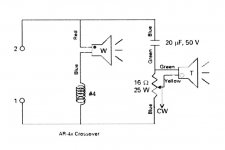
Here is schematic of the classic Acoustic Research AR4x. It is a two-way acoustic suspension design with both drivers nominal 8 ohms impedance. The variable attenuation feature on the tweeter is provided bya 16 ohm rheostat. 15 ohm rheostats are available today from electronic suppliers. They are still made by Ohmite and others.
8 ohm L-pads are also common devices for obtaining variable attenuation of an 8 ohm tweeter. These are more common and usually come with instruction for wiring them up to a speaker.
8 ohm L-pads are also common devices for obtaining variable attenuation of an 8 ohm tweeter. These are more common and usually come with instruction for wiring them up to a speaker.
Attachments
Tank you.
I am trying to make a exact replica of the filter given in the 2 different articles below
http://www.sixmoons.com/audioreviews/wlm/divamonitor.html
http://www.wlm-loudspeakers.com/DIVA_MONITOR_STEREO_Review_10_2006.pdf
Just with better components
But I am having a hard time finding the values of the different components. The only thing I know for sure is the xo frequency and that is 1500Hz.
The pictures suggest that the attenuation of the treble is done by a resistance network as suggested in
http://www.sengpielaudio.com/calculator-Lpad.htm
But then what the diagram from speakerdoctor suggests something completely different?
Im unsure here?
Further, if looking at the measurements in the article provided by stereo suggests that the w impedance is 4 ohm rather than 8 which might explain the resistor connected to the capacitor connected to the coil on top of the attenuator. Or what is that used for ?
If both w and t where 8ohm I would assume the following values
Capacitor 13.25 microfarads (standard value 10 or 15 microfarads
Coil 0.85 millineries
So if both where 8 ohm I would assume the filter was composed of the following standard components:
15 milifarad for the highpass capacitor
0.82 miliheries for the lowpass coil
If it instead was a w 4ohm and tweeter 8 ohm i would end up with
Capacitor 13.25 microfarads
Coil 0.42 millineries
Which would then translate into:
15 milifarad for the highpass capacitor
0.47 or 39mh miliheries for the lowpass coil (Any thoughts?)
Any thought on the basics of the low and high ?
Further, looking at the measurements of the speaker itself with tweeter (http://www.performanceaudio.com/media/pdf/264/4173_s.pdf)
compared to the measurements of the article suggest the base attenuation is in the region of 10 db and then variable to -19 making me think something like
R serial = 5.47 ohms – 7.01 ohms
R parallel = 3.7 ohms – 1 ohms
So
R serial = 6 ohms ????
And rotary potentiometer for 4-1 ohm ??
That is all my wits but I got no idea! Pleas help with thoughts even though the above might seem a bit blurry. Thanks!
- Status
- This old topic is closed. If you want to reopen this topic, contact a moderator using the "Report Post" button.