The article is based upon all of the references given but significantly the boundary element simulations of Johansen.
These simulations include horns with two and three conical sections in various proportions and these show some general trends..
For instance the two conical section device shows a lessening of the low frequency narrowing characteristic of plain conical horns along the lines originally pointed out by Keele, and the three conical section horns are generally better in this respect.
This lead me to the conclusion that a device that replaces the outer conical section with a radius that meets both baffle and conical section at right angles will confer the lessening of the finite aperture diffraction effect noted by Earl Geddes as well as have constant directivity down to a frequency lower than that of a plain conical horn, (as noted by Keele), measurement shows this is generally true.
If for instance the three conical section device has the three sections replaced by a single arc passing through the end points of these sections, then the directivity is that of the three conical section devices modeled by Johansen, but does not have the diffraction at the joins that such a device will have.
The area growth function in the article is for such a device.
What we in fact have is not a single device but a family of devices that we can legitimately make from two or three conical sections, replacing the outer parts of some or all with circular arcs.
That is not to say that all will be identical in measurement but they are near enough so that the actual shape and breakup characteristics of the driving dome will probably play the largest part in the measured performance.
From the above it seems reasonable to suppose that we can we can construct a family of non axis symmetric device
using the same area expansion rules.
My reference to the rectangular section with semicircular ends comes about if you look at the wavefront that is being produced by the asymmetry of the axiis.
It is normally supposed that the best shape for a non symmetric device is an ellipse.
The is stated reasons for this seem to be along the lines that the circle is just an ellipse with identical major and minor axiis and if the waveguide has an exact or near exact wave equation solution with a circular cross section then the elliptical solution will be not too far away, and that overall this is a good thing, (although exactly why is not stated, implying that the reason is far too obvious, and I am not sure that it is)..
What we are asking for however is a wave front that is some hybrid of a spherical cap and a cylinder and some crude back of the envelope calculations on my part seem to indicate that a better mapping exists between the wavefront as it comes from the dome and the aforesaid figure than exists between said wavefront and an ellipse.
If this is so then and a measure of higher mode production is the amount by which the notional spherical cap coming of the dome is distorted, then the semicircular ended rectangle may well reduce higher order mode production, and is easier to make.
Below is a win isd model of a Seas 29mm. driver that has a rated peak excursion of 0.5mm.
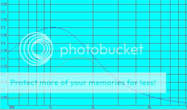
The blue is a 2nd. Order Butterworth filter at 1.5kHz. the red a 4th. order L-R at the same frequency, the input is a 180 Watt peak.
This can be expected to produce peaks of around 116db. with compensation in a shallow waveguide.
Some measurements I did in my own home indicate that I and other people are comfortable with an maximum 85db. average spl. on a wide range of music the maximum peak was 115db. measured with a "c ", weighting scale, and around 10millisecond time constant.
As can be seen this tweeter should be well capable of doing this from a excursion viewpoint, even with a second order filter.
rcw.
These simulations include horns with two and three conical sections in various proportions and these show some general trends..
For instance the two conical section device shows a lessening of the low frequency narrowing characteristic of plain conical horns along the lines originally pointed out by Keele, and the three conical section horns are generally better in this respect.
This lead me to the conclusion that a device that replaces the outer conical section with a radius that meets both baffle and conical section at right angles will confer the lessening of the finite aperture diffraction effect noted by Earl Geddes as well as have constant directivity down to a frequency lower than that of a plain conical horn, (as noted by Keele), measurement shows this is generally true.
If for instance the three conical section device has the three sections replaced by a single arc passing through the end points of these sections, then the directivity is that of the three conical section devices modeled by Johansen, but does not have the diffraction at the joins that such a device will have.
The area growth function in the article is for such a device.
What we in fact have is not a single device but a family of devices that we can legitimately make from two or three conical sections, replacing the outer parts of some or all with circular arcs.
That is not to say that all will be identical in measurement but they are near enough so that the actual shape and breakup characteristics of the driving dome will probably play the largest part in the measured performance.
From the above it seems reasonable to suppose that we can we can construct a family of non axis symmetric device
using the same area expansion rules.
My reference to the rectangular section with semicircular ends comes about if you look at the wavefront that is being produced by the asymmetry of the axiis.
It is normally supposed that the best shape for a non symmetric device is an ellipse.
The is stated reasons for this seem to be along the lines that the circle is just an ellipse with identical major and minor axiis and if the waveguide has an exact or near exact wave equation solution with a circular cross section then the elliptical solution will be not too far away, and that overall this is a good thing, (although exactly why is not stated, implying that the reason is far too obvious, and I am not sure that it is)..
What we are asking for however is a wave front that is some hybrid of a spherical cap and a cylinder and some crude back of the envelope calculations on my part seem to indicate that a better mapping exists between the wavefront as it comes from the dome and the aforesaid figure than exists between said wavefront and an ellipse.
If this is so then and a measure of higher mode production is the amount by which the notional spherical cap coming of the dome is distorted, then the semicircular ended rectangle may well reduce higher order mode production, and is easier to make.
Below is a win isd model of a Seas 29mm. driver that has a rated peak excursion of 0.5mm.
The blue is a 2nd. Order Butterworth filter at 1.5kHz. the red a 4th. order L-R at the same frequency, the input is a 180 Watt peak.
This can be expected to produce peaks of around 116db. with compensation in a shallow waveguide.
Some measurements I did in my own home indicate that I and other people are comfortable with an maximum 85db. average spl. on a wide range of music the maximum peak was 115db. measured with a "c ", weighting scale, and around 10millisecond time constant.
As can be seen this tweeter should be well capable of doing this from a excursion viewpoint, even with a second order filter.
rcw.
While searching the internet I found a german article from an acoustic institute.
http://www.akustik.rwth-aachen.de/pub/mma/mma_daga03_vor.pdf
In principle this contains what I was asking for according to acoustic impedance although I can not simulate with BEM the directivtiy.
The picture 7.2 shows the development stages/optimization when moving from a spherical horn to something else while remaining the expansion rule the same.
Picture 7.8 is the directivity of the spherical horn, while 7.6 (horizontal) and 7.7 (vertical) are the directivities of the new horn geometry.
@rcw: Which Seas driver did you use for simulation?
@gedlee: For which purpose do you construct this horn? PA or hifi?
The tweeter I used in the simulation is the Seas Magnum T29F001E0047.
I used this one because it has the longest linear excursion,( at 1.4mm. peak to peak), that I could find.
The transform in the reference is a geometry that I have also in fact built, that is flat circular horizontal sections joined by a constant radius fillet of the same radius as the throat.
Unfortunately the data was on a hard drive that gave up the ghost, but from memory the frequency response resembled that of the quadratic throat type of waveguide with a slight hump in the middle.
rcw.
rcw said:
What we are asking for however is a wave front that is some hybrid of a spherical cap and a cylinder and some crude back of the envelope calculations on my part seem to indicate that a better mapping exists between the wavefront as it comes from the dome and the aforesaid figure than exists between said wavefront and an ellipse.
If this is so then and a measure of higher mode production is the amount by which the notional spherical cap coming of the dome is distorted, then the semicircular ended rectangle may well reduce higher order mode production, and is easier to make.
Hi RCW
I'm having trouble making out what exactly you are saying. I don't think that the above paragraphs make much sense, or at least I don't understand them.
In the case of a conical horn, (i.e. the exact waveguide for a spherical wave), we can construct the wave front further down the wave guide by a set of orthogonal equal length vectors emanating from the cap surface.
The geometry of the wavefront we subsequently construct is invariant under this mapping, i.e. it is simply a larger version of the one we mapped from.
If we now look at the situation where we want to map from a spherical cap to a wavefront , say 40x90 degrees.
What we find is that the centre and the plus and minus x,y coordinates that define the wavefront center the orthogonal boundary extremes around it are again invariant under this mapping for all boundary shapes, but the shape of part of the wavefront that lies between these points is determined by the shape of the boundary.
I ask myself given this case what boundary shape yields a wavefront that is most similar to a spherical cap.
I cannot find a reason why it should be an ellipse, perhaps you can suggest why it is?
rcw
rcw said:
What we find is that the centre and the plus and minus x,y coordinates that define the wavefront center the orthogonal boundary extremes around it
are again invariant under this mapping for all boundary shapes, but the shape of part of the wavefront that lies between these points is determined by the shape of the boundary.
Could you please restate the first part, above the break I've inserted, I can't parse it. Is there a word missing between the 2nd "center" and "the orthogonal"?
Ken
No Ken, I will leave it just as it is.
The overall point is that the major features of the wavefront remain in tact no matter what the cross section is.
Most threads about non axis symmetric waveguides seem to assume that an elliptical cross section is needed, and this is a major stumbling block since it is hard to make.
But I have seen no real proof that the ellipse is best and there might well be other shapes that are at least as good or even better, and are easier to make, so why does the discussion always seem to end with the desirability of an ellipse and then put the whole matter in the too hard basket, when something else might well serve just as well, (although it may not have quite the aesthetic appeal of the ellipse).
rcw.
I'm still not sure that I follow your discussion, but to your question, there is nothing magic about an ellipse. A spherical wavefront can also be defined on a rectangular cross section. In fact if one wants to analyze the directivity of a non-axi-symmetric wavefront it is far easier to do it from a rectangular surface than an elliptical one.
I discuss this in one of my patents, if you just search those.
The rectangular mouth will not "map" to a spherical far field as well as an ellipse will however fo the obviuos reasons that a rectangle is not as simplar to a cirlce as an ellipse is. What this means in practice is that the polar patern for a rectangle will change differently across the diagonal than across the side centers - the radiation pattern isobars will not be ellipses. With an elliptical cross section they will.
As to "making" them, I don't see the square cross section as any easier to do.
For very different radiation angles, such as 120 x 30, the rectangular does have some advantages, but not for closer angles like 60 x 90.
What I am talking about can be illustrated by this diagram..
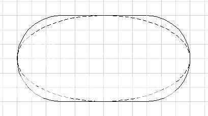
This is a comparison an ellipse of aspect ratio 2:1, and a rectangle with semicircular ends of the same aspect ratio.
As you can see the maximum difference across the diagonals is about on tenth of the total width.
In a diy context the rectangular figure is much easier to make since it but two hole saw cuts joined by jigsaw cuts.
Making the interior part before the mouth radius a conical section has the advantage that the surface between the round throat and the end of the conical inner section is ruled and therefore can be formed by filling the intermediate void and using a straight edge between the two end forms as a forming tool.
The original question in this thread was how one would go about forming an elliptical wave guide directly in the baffle, this is an easy method of forming a near elliptical one that anyone should be able to do.
The question then arises how does the performance of this easy to make pseudo elliptical waveguide differ from some ideal elliptical shaped one? : I suspect the difference will be arbitrary.
rcw.
I can't tell if you're being facetious here.cotdt said:actually the elliptical profile is easier to make. just rip out the cone from an Excel W22 and use that as your waveguide.
dlneubec said:You can have both great sound and great aesthetics, IMO. I'm sure some don't care what their car looks like, since they only drive it, or what their home looks like since they only live in it, etc. Personally, I certainly care how what I create looks like, including speakers. I care what my speakers sound like even more, but I prefere not to settle aesthetically. YMMV.
<snip>
Dan...
Your work speaks for itself. I wouldn't be too concerned with others' agendas, since you CLEARLY state this is a DIY modification, and you've presented a technique that can make improvements w/o major visual impact.
Looking forward to hearing the BaSSlines in lexington.
John L.
A satellite speaker system I made that features a 3kHz. axis symmetric waveguide is here..
http://sound.westhost.com/articles/ssl1.htm
The frequency response of the finished system is below..
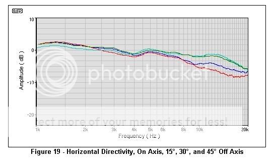
The waveguide is designed to have 90degrees of directivity above 3kHz. using the formula in my waveguide article.
As you can see the maximum deviation from on axis to 45 degrees of axis from 3kHz. out to 20kHz. is 6db.
The waveguide is of the single radius sort and the initial slope at the throat has an included angle of 90 degrees.
The throat has the same area as the manufacturers rated diaphragm area and the throat is extended downwards to clear the surround by 0.5mm.
rcw.
http://sound.westhost.com/articles/ssl1.htm
The frequency response of the finished system is below..
The waveguide is designed to have 90degrees of directivity above 3kHz. using the formula in my waveguide article.
As you can see the maximum deviation from on axis to 45 degrees of axis from 3kHz. out to 20kHz. is 6db.
The waveguide is of the single radius sort and the initial slope at the throat has an included angle of 90 degrees.
The throat has the same area as the manufacturers rated diaphragm area and the throat is extended downwards to clear the surround by 0.5mm.
rcw.
Am I too late toask a question?
What would be the optimal waveguide size if I were trying to design an MTM? I need to tradeoff center-to-center distance, crossover frequency, and waveguide size.
Thanks!
gedlee said:In my experience bigger is better. You will get an effect from even a small waveguide, as noted, but the larger the device the more well controlled the directivity will be and the lower in frequency and the greater gain you will achieve -
What would be the optimal waveguide size if I were trying to design an MTM? I need to tradeoff center-to-center distance, crossover frequency, and waveguide size.
Thanks!
It may be that the architect Gaudi can show us the way. I believe he suspended light films, maybe even soap bubble from frames, to come up with some of the shapes he used. Maybe if a wire frame was made at the point in which the elliptical shape becomes established and then a light thin film, or soap bubble., in the desired throat shape was pulled down to the required legth and photographed, it would establish how to smoothly change the contour. I'm nowhere near being a physicist or mathematician so have no idea whether this is practical or not.
There is website somewhere which shows a way of doing laser 3 dim. photographs which may be of use also.
jamikl
There is website somewhere which shows a way of doing laser 3 dim. photographs which may be of use also.
jamikl
weinstro said:What would be the optimal waveguide size if I were trying to design an MTM? I need to tradeoff center-to-center distance, crossover frequency, and waveguide size.
The mouth needs to be at least a wavelength across for good pattern control at the lower edge of the passband, i.e. the crossover point. Smaller than this and the pattern will narrow and then widen again. You have to make the "tradeoffs" yourself.
The mathematical name for the soap film is a catenoid - a surface or line which is minimal in some respect - total tension in the case of the soap film. The Oblate Spheriodal waveguide is a catenoid of the surface connecting two aperatures - the throat and the mouth.
gedlee said:
The mouth needs to be at least a wavelength across for good pattern control at the lower edge of the passband, i.e. the crossover point. Smaller than this and the pattern will narrow and then widen again. You have to make the "tradeoffs" yourself.
Thanks for the guidelines. Really, like 7.5" at 1.8kHz? Seems like this won't work with MTM -- need to pick one approach or another.
Thanks again!
If you first take Art Ludwig's approximation for directivity then a nominally eight inch driver with a effective cone diameter of .165m. has..
(58*0.23)/.165 = 81 degrees at 1.5kHz.
This is close enough so that we can use a 90x40 degree waveguide.
By Linkwitz's expression the center distance of our woofers can be
(1/.342 )*.115 = .336m. center to center for a 40 degree beam.
For a nominal 8inch driver we will have about .13 meters between driver edges and we can perhaps use 100-110mm. as our mouth height.
By Keeles expression we get a lower constant vertical directivity frequency from..
25306/(40*.110) = 5.75kHz.
This is for a plain conical horn and flared moth and circular radius devices are somewhat better so we can say that the -3db. 40degree point will occur at around 4.5kHz.
You can of course use 6-6.5 inch drivers at the same spacing to fit a larger 0.16m. vertical dimension waveguide in which case you can reduce the waveguide vertical cut off to the 3.2kHz. region.
The later will probably give smoother overall results, but with less power handling and extension at the low end.
rcw.
Or - you could just use one woofer which would allow a much lower crossover point and much better overall polar control while sacrificing some vertical control. Since the vertical control is far less important than the horizontal, to me the single woofer tradeoff is the much better choice than MTM.
- Status
- This old topic is closed. If you want to reopen this topic, contact a moderator using the "Report Post" button.
- Home
- Loudspeakers
- Multi-Way
- How to construct a elliptical waveguide for a tweeter?