Just a short query and conjecture.
i've just read through the Pi Speakers article on cooling high power woofers.
When testing my current project, (OB with cheapo woofers and old japanese 8inch midrange ), the backplate on the mid was getting very hot.
I moved the crossover frequency up a bit and changed the slope a bit and that helped but midrange was still getting much hotter than the bass units.
I am considering a quick fix using silver epoxy and a couple of old heatsinks from computer chipsets.
These old Coral 8inchers sound too good to destroy, has any-one tried this?? and if so what difference did it make??
I will of course make my personal findings known but they will be subjective as I don't hav a sensor that I can fit to the back plate easily.
regards
ted
It can't hurt can it? The only thing I've seen (diy? I'm not sure) was a heatsink stuck to the back of a TB neo tweeter.
This one:
http://www.partsexpress.com/pe/showdetl.cfm?&Partnumber=264-804
Sammi did this to their 12" coax
This one:
http://www.partsexpress.com/pe/showdetl.cfm?&Partnumber=264-804
Sammi did this to their 12" coax
Attachments
A while back I had an idea of voice coil cooling by heat pipes. A heat pipe would go into a vented pole piece and transfer heat effectively to a large heat sink in the back panel.
I also found an old japanese AES paper on the subject, only that they had the radiator in the port of a ported box (for airflow = cooling). They could double the continuous power handling by using the method.
However, it doesn't look like it would be easy to pull off as DIY. One would need a heat pipe manufactured to fit the dimensions of an existing woofers pole piece. This would be more suited to commercial loudspeaker manufacturers who could manufacture all parts to specification themselves.
One possible DIY option would be a screw threaded woofer vent with the possibility to stick whatever length and shape of heat pipe provided it has a matching screw thread on one end.
Hi breez, thats how Pi did them but with a large passive plate as the heat exchange inside the box.
As I can't abide throwing anything away ( Hey!! It may come in useful iff'n I keep it long enuf ) I have rather a large collection of used heatsinks here.
West Systems epoxy may also be used here i would say but I haven't been able to find any data on the thermal resistance of aluminium filled epoxy.
This is an open baffle cabinet...right?
You may not be aware of this, but those who push there computers to the limit, and those who don't like fan noise, use water cooling in place of fan cooling on their processors.
An aluminum plate is attached to the processor with tubes running to a radiator, and the fluid (it's actually not water) is pumped through the system.
These are very effective cooling devices, so effective that one of the problems is occasion condensation of water on the tubing.
Just a thought.
Steve/bluewizard
Yes Steve in this instance it's an open baffle, but in principal you could apply this sort of cooling to any speaker.
Even if the voice coil is centre vented I have seen heatsinks that could be drilled out, leaving the hole uncovered but still enough contact around the edges.
I have a son who is into computers in a big way and I've seen those water cooled radiators, some of the new computer chips run "HOT" but that is going too far for speakers, think of the pump noise raising the floort hreshold by 12dB
I read that a while ago, not long after I finished my LABhorns from memory. Whilst it seemed to be an issue in Pro use, mine certainly never even got warm. As I'm going to be using the second NOS set for some PR subs, I may mount them magnet out to keep them cooler.Moondog55 said:i've just read through the Pi Speakers article on cooling high power woofers.
Can't see why it would make much difference OB, but as it's free, try it and tell us your results.
I also like the idea of some external cooling system, but I'll keep that experiment for later with my bass guitar cabs.
Hi Brett!
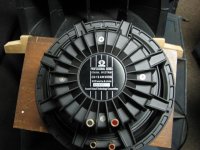
I was surprised at how hot the Corals were getting when I started to put more than a couple of watts thru them.
These are an older driver and the dust caps are sealed so no ventilation ( these drivers may have been modified by the last owner to improve HF radiation ) but they were HOT to touch 88 +, and as I have all the stuff here why not??
Moving the X-over up a touch and making the slope a little steeper so less movement in the driver probably means more.
As this is experimental I wanted to use what I had on the shelf, so cross-overs were determined not by driver performance but by what inductor I had in my tool box ( in this case the cheap laminate cored unit from Jaycar 9.**mH )
I can actually see a time in the future when watercooling PRO gear makes sense, the cost of the required hardware is going down faster and faster.
It must make some difference as the little Vifa neo I have had them designed in from the get-go.
Don't sell the CPU cooling idea short. There are fanless heatpipes available.
As an example -
http://www.mwave.com/mwave/viewspec_v2.asp?scriteria=BA25303
http://www.mwave.com/mwave/viewspec_v2.asp?scriteria=BA25253
http://www.mwave.com/mwave/viewspec_v2.asp?scriteria=BA24346
http://www.mwave.com/mwave/viewspec_v2.asp?scriteria=BA24678
http://www.syba.com/Product/Info/Id/255
It's just a thought.
Steve/bluewizard
Moondog55 said:West Systems epoxy may also be used here i would say but I haven't been able to find any data on the thermal resistance of aluminium filled epoxy.
Stycast 2850 mt with catalyst 11:
.0045 cal-cm/sec-cm^2 C
Copper has a value of .94
I prefer watts/degree C-inch, I refer to this as "K"...copper is 10.2, 2850 epoxy is .0488.
To use these numbers, apply thusly..
thickness /area times K.
A copper cube 1 inch is 1 / K = .098 degrees c per watt.
A copper shim 1 inch by 1 inch by .050 thick is:
.05 / K or .0049 degrees C per watt.
An epoxy bond 50 mils thick and 1 inch square:
.05 / K or .05/.0488 = 1.02 degrees c per watt.
A 2 inch diameter circle of epoxy (3.1415 square inches) 50 mils thick:
.05 / (3.1415 * .0488) = .326 degrees c per watt.
Cheers, John
ps..other K's
aluminum 5.3
copper 10.2
gold 8.06
lead .9
silver 10.84
tin 1.73
alumina .94
beO 6.3
pb/sn 1.25
")
No problem, glad to help.
I work with epoxies a lot, and my current applications involve liquid helium, so I've had to learn a lot.. I've worked with many cryo and rad hard epoxies structural and non structural, as well as encapsulation of military diode assemblies... and you know what the most consistent thing I have found is???
West systems is the best. No holds barred.
When you make your first batch with more powder than recommended, try a test build on fake parts. You may find that overloading the epoxy causes the mix to go dry, which will cause the bond to fail easily.
Cheers, John
Moondog55 said:Just a little OT but if you wanted to make a good low mid driver , what is better fot the high frequencies?? a whizzer cone or a big dome, looking at this driver I think the woven vent cap was replaced as these are big and heavily textured soft paper.
How about removing the dust cap, and install a copper phase plug?
Loudspeaker Venting and Cooling Techniques
My initial assumptiuon and first prototype used exactly this method. In hindsight, I should have done some exploratory experiments to see which of the three heat paths most of the thermal energy was transferred by. But instead, I started with an assumption that forced air cooling would be the best approach and built a prototype cooling system that used the speaker as a pump and had ducts to a heat exchanger.
My idea was to introduce unidirectional airflow, so that there was a hot air exhaust and a cool air input to the voice coil gap. The air would be cooled with an intercooler, or alternately, could be provided with a fresh cool air source, such as being vented to ambient.
Venting to ambient is easier, but it allows airflow from the rear of the cone out the vent, effectively creating a leak. This could be solved either by sealing the gap or by sealing the cooling system. If the cooling system was sealed, it essentially adding the volume of air in the cooling system to the rear chamber volume, through a small passage, the air gap. The sealed cooling system has a pair of ducts to an intercooler, which serves to radiate heat away from the system.
The trick was to use the woofer as the air pump without creating an asymmetrical force bias that would affect cone motion. The resistance to airflow that created pump action must be the same whether the cone was moving forward or back. This is fairly simple with a vane-valve like shown above. It provides more airflow resistance one way than the other, working like a diode. A pair of these vanes makes a two-way valve which provides an input path and an output path without allowing unequal pressures to develop, biasing the cone forward or back.
After building the valve, I noticed two things almost immediately. The first thing was it worked very well at introducing unidirectional flow, allowing the speaker to work as an air pump without causing asymmetrical cone motion. The second thing I noticed was that the air passing through the ducts wasn't heated much at all, even if the voice coil was nearly at the point of thermal failure. Since the air wasn't heated much, the intercooler approach is not particularly effective, nor is venting to ambient.
This caused me to rethink everything, and start doing some measurements of heat flow in the loudspeaker. Forced air convection cooling does work, and it works well. The existing vented gap approach is a pretty good idea. But it relies on high airspeed, which is accomplished largely because the gap is so small. If you increase airspeed, you could improve the convection cooling, but you would also introduce pressure changes across the cone and increase turbulence, possibly to the point of audibility. A static air pump can't be used because it will bias the cone one way or another, causing it to be deflected from center, intruducing asymmetry and distortion.
The existing venting arrangement in woofers works pretty well, when properly sized and positioned. It's like tuning the exhaust of a car, you match the velocity of the vent with the frequency range you expect the device to work in. So it works well through a range of frequencies, provided cone excursion is providing some pumping action. Where this falls apart is at higher frequencies where cone motion is reduced, or when used in a loudspeaker that acoustically loads the cone and limits excursion, like basshorns.
The voice coil is in close proximity to the pole piece, so there is heat radiation across the gap. There is also direct heating of the core, caused by inductive heating of the magnetic structure. These two things combine to generate a LOT of heat in the motor core, primarily in the center pole piece. That's where a significant improvement can be made. Most speakers suffer a huge amount of heat build-up in the core, which is essentially an iron cylinder surrounded by ceramic, practically a thermos bottle that holds in heat. Put a few hundered watts in to the voice coil, and there's a lot of heat produced, even in the most efficient loudspeakers. Think of the heat generated by your soldering iron, multply that tenfold and hold it in a thermos bottle. That's the environment the voice coil lives in.
After realizing this, it made my job a LOT easier. Simply conduct heat away from the pole piece, and dissipate it into a large heat sink. That simple system will do a world of good. The heat sink can double as an access panel, or it can be attached to the rear of the speaker. Obviously, it is best to get the heat out of the box, so an access panel or other external mounting arrangement is preferred. But the most important thing is to get the heat out of the core.
breez said:A while back I had an idea of voice coil cooling by heat pipes. A heat pipe would go into a vented pole piece and transfer heat effectively to a large heat sink in the back panel.
My initial assumptiuon and first prototype used exactly this method. In hindsight, I should have done some exploratory experiments to see which of the three heat paths most of the thermal energy was transferred by. But instead, I started with an assumption that forced air cooling would be the best approach and built a prototype cooling system that used the speaker as a pump and had ducts to a heat exchanger.
My idea was to introduce unidirectional airflow, so that there was a hot air exhaust and a cool air input to the voice coil gap. The air would be cooled with an intercooler, or alternately, could be provided with a fresh cool air source, such as being vented to ambient.
Venting to ambient is easier, but it allows airflow from the rear of the cone out the vent, effectively creating a leak. This could be solved either by sealing the gap or by sealing the cooling system. If the cooling system was sealed, it essentially adding the volume of air in the cooling system to the rear chamber volume, through a small passage, the air gap. The sealed cooling system has a pair of ducts to an intercooler, which serves to radiate heat away from the system.
The trick was to use the woofer as the air pump without creating an asymmetrical force bias that would affect cone motion. The resistance to airflow that created pump action must be the same whether the cone was moving forward or back. This is fairly simple with a vane-valve like shown above. It provides more airflow resistance one way than the other, working like a diode. A pair of these vanes makes a two-way valve which provides an input path and an output path without allowing unequal pressures to develop, biasing the cone forward or back.
After building the valve, I noticed two things almost immediately. The first thing was it worked very well at introducing unidirectional flow, allowing the speaker to work as an air pump without causing asymmetrical cone motion. The second thing I noticed was that the air passing through the ducts wasn't heated much at all, even if the voice coil was nearly at the point of thermal failure. Since the air wasn't heated much, the intercooler approach is not particularly effective, nor is venting to ambient.
This caused me to rethink everything, and start doing some measurements of heat flow in the loudspeaker. Forced air convection cooling does work, and it works well. The existing vented gap approach is a pretty good idea. But it relies on high airspeed, which is accomplished largely because the gap is so small. If you increase airspeed, you could improve the convection cooling, but you would also introduce pressure changes across the cone and increase turbulence, possibly to the point of audibility. A static air pump can't be used because it will bias the cone one way or another, causing it to be deflected from center, intruducing asymmetry and distortion.
The existing venting arrangement in woofers works pretty well, when properly sized and positioned. It's like tuning the exhaust of a car, you match the velocity of the vent with the frequency range you expect the device to work in. So it works well through a range of frequencies, provided cone excursion is providing some pumping action. Where this falls apart is at higher frequencies where cone motion is reduced, or when used in a loudspeaker that acoustically loads the cone and limits excursion, like basshorns.
The voice coil is in close proximity to the pole piece, so there is heat radiation across the gap. There is also direct heating of the core, caused by inductive heating of the magnetic structure. These two things combine to generate a LOT of heat in the motor core, primarily in the center pole piece. That's where a significant improvement can be made. Most speakers suffer a huge amount of heat build-up in the core, which is essentially an iron cylinder surrounded by ceramic, practically a thermos bottle that holds in heat. Put a few hundered watts in to the voice coil, and there's a lot of heat produced, even in the most efficient loudspeakers. Think of the heat generated by your soldering iron, multply that tenfold and hold it in a thermos bottle. That's the environment the voice coil lives in.
After realizing this, it made my job a LOT easier. Simply conduct heat away from the pole piece, and dissipate it into a large heat sink. That simple system will do a world of good. The heat sink can double as an access panel, or it can be attached to the rear of the speaker. Obviously, it is best to get the heat out of the box, so an access panel or other external mounting arrangement is preferred. But the most important thing is to get the heat out of the core.
Wonderful information Wayne.
Of course your original idea may work if you added a pump in adition to the external radiator.
The aluminium powder hasn't arrived yet, so no progress.
As you have done all the work what opinion do you have on the effectivness of the simple solution, just glueind a heat sink to the backplate??
Regards
Ted
Forced air convection cooling using an external pump on a voice coil driven speaker is not a particularly good idea, in my opinion. While it would provide additional cooling, it would also greatly increase the complexity. Another problem is unless the voice coil gap is sealed, the pump pressure would exert a force on the cone, which would offset its center. This creates asymmetry and ultimately increases distortion.
Tom Danley used an external pump on his commutated speakers, and in that application, it works. The motor is a sealed DC motor, so pressure inside it is isolated from the cone. The cone is driven by a pully and a belt, and the motor is sealed, so in that application, an external blower can be implemented without too much complexity. But voice coil driven speakers don't work as well in this arrangement, because the motor is not sealed. Pump pressure applied in the gap moves the cone. That's not something you want to do. So applying this same approach to voice coil driven loudspeakers was not a good idea.
There was a patent for an external pump on a voice coil driven speaker, applied for by Bruce Howze of Community Professional Loudspeakers. He did it right - The voice coil gap is sealed from the front and rear of the cone, so pressure can be applied without moving the cone. But the system was complex enough it cost too much money. It was a matter of dimishing returns, the amount gained wasn't worth the added complexity and increased cost. Better to increase power handling and reduce compression different ways, even brute force using larger parts.
That's why the cooling plug and plate idea is so appealing to me. It is simple and it is effective. The passive vented gap arrangement already employed does its job nicely, providing forced air convection cooling. Since the air coming from the vents isn't particularly hot, it's already doing it's job pretty well. Leave that and add cooling plugs and plates. This addresses the problem that remains - heat radiated into the pole and direct heating from magnetic induction. It works so well, in fact, that I applied for a patent on it.
As for the position of the heat sink, that matters far less than the thermal interface. That's what you want to focus on. The best heat transfer comes from the center pole, not the back plate. So don't just attach something to the rear plate, fabricate a plug that runs along the inside of the center pole piece. Make it hollow with side vents so the cooling vent is not obstructed. Attach the cooling plug to your heat sink, which can be mounted on the back of the speaker.
Be sure the cooling plug contacts the entire center pole, run through all the way with as much surface area contact as possible. Machine the plug to fit snugly. If you're lucky, the center pole ID will be uniform and you can simply sand the paint off, apply heat conductive grease and insert the plug. If not, if the pole piece ID is not uniformly round, either have it machined or drill it out with a drill press. Machining is preferred, because you can achive a closer tolerance, something like a brake cylinder and piston would be ideal. A drill press will leave grooves, but it still works very well.
When machining, the magnet works for you, tending to capture the debris. But do be careful to bring the debris to the surface, not down into the gap. I thought at first this would be hard to do, to machine a speaker that was already assembled. Naturally, I would have preferred to only work with parts prior to having the cones installed. But I have found that it isn't difficult to take a thin layer off the ID of the center pole, just enough to true it up, without getting debris in the gap. A drill press and a large bit is all that is really required for a DIYer.
Wayne Hi! and thanx
What if there is no existing pole vent as is the case with most older drivers that have a sound that I find engaging and eminently listenable??
As most of my early drivers have relatively small voice coils (most of mine are 1inch), would you say that a 1/2 inch hole that isn't full depth would work?? Could a 3/8 inch hole work if a short length of copper pipe was used??
These are just questions thrown into the ring for general comment.
I am a little reluctant to work on a speaker that sounds good in fear of doing damage I can't repair.
With the pump idea I was actually thinking of a seperate radiator mounted on the exterior of the speaker box and the pumps only job being to transport hot fluid from one place to another; how you collect the heat at source is another matter, I can see your heat sink in a sealed bath of polyetheylene glycol and an associated silent pump moving the heated liquid to an area where that heat be dissipated more rapidly, perhaps using another quiet fan, after all given air flow and liquid cooling a few hundred watts isn't a lot, think of the amount of heat generated by your average trail bike
Many thanks for your insight and the hard work you've already done
If you have no vent, then the pole piece is solid. That being the case, you could attach a heat sink directly to the rear plate. Be sure to clean both surfaces removing paint, decals, etc. Use heat sink compound between the two surfaces and clamp with as much pressure as feasable. The more surface area contact, the better.
If these speakers are expensive and/or rare, I'd probably stop there. But if they're not real expensive and available as current production units, I'd suggest modifying them exactly like you describe. The center pole is iron or low carbon steel, so you can cut into it and replace some of it with a metal that has less thermal resistance. Cut down close to the front plate for best results - the voice coil surrounds the center pole closest to the front plate. You can even tap the hole and form your cooling plug with a die so it can be thread in place. This will do a lot better job of sinking the heat away, and may also provide some flux stabilization properties, like a Faraday ring.
The downside is you will be modifying the magnetic circuit as a result, which will cause electro-mechanical parameters to shift. If the center pole is close to saturation in the unmodified driver, then your mods will probably cause it to saturate easier, at lower drive levels. But I don't expect that is the case. The limiting factor in the return circuit is probably the plates. Still, by taking "meat" out of the pole piece, you will be changing the magnetic circuit, so you will want to do some measurements to see what you are left with. This will let you size the plug according to your needs.
- Status
- This old topic is closed. If you want to reopen this topic, contact a moderator using the "Report Post" button.
- Home
- Loudspeakers
- Multi-Way
- Voice coil cooling