I use SnagIt 5.0 to capture the active window and save it as a gif in a folder, then use the forum's upload feature to post it, but this requires a separate post for each 'capture', so some folks make a collage of the various captures:
GM
GM
Attachments
And finally
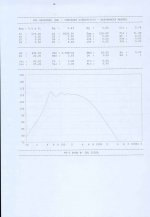
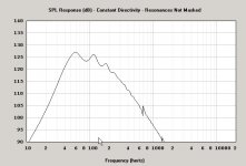
Here's the measurements as taken at the horn mouth on the prototype back in 1978..
Would be very interesting to get some comments on how you think the modeled response and the measured response compare!
If this validates the model to the point where it can actually prove useful for evaluating modern day driver candidates, that would be just great!
Attachments
Shouldn't I go to bed so I can get up and go to work tomorrow??
All geared up now...
Just did some quick simulations with both the Eminence kappa 12 and the Pioneer woofer (mentioned earlier). Efficiency seems pretty similar, but the pioneer woofer actually seems to give a smoother response!
The only drawback I can find with the pioneer is that at 20V input, its on the limit of its 2,5mm Xmax, but heck.. thats at allmost 130 dB output!!!
Yes, that's what the SPL plot tells me, 130 db... DOWN TO 40 Hz!! can this really be true??
I have to build one of these babys.. and if the landlord complains, I can just turn up the volume.. until he melts, AHAHAH!!
Re: And finally
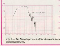
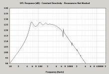
It doesn't for me. Since HR sometimes seems to over emphasize 'ripple' I loaded it into MJK's old FLH designer which tends to show a better damped response, but it simmed 'close enough' to convince me we're missing a major 'something' based on the actual measurement:
GM
Elbert said:
If this validates the model.......
It doesn't for me. Since HR sometimes seems to over emphasize 'ripple' I loaded it into MJK's old FLH designer which tends to show a better damped response, but it simmed 'close enough' to convince me we're missing a major 'something' based on the actual measurement:
GM
Attachments
Hi GM!
Hmm... yes.. this looks a bit different again... hard to say if its just a measurement technicality or some fundamental discrepancy with the model..
Volume-wise, the model also seems quite close to the original design..
Problem is that I've got no more data left to extract from the original design for further model input...
But, if we take the "worst case" and assume that the model is at best an approximation of the actual horn.. could it still be used as a "test-bench" for evaluating drivers?
In other words, would a driver showing good response in the model also be likely to work well in the real horn?
Greets!
If you're satisfied that you've calculated throat/mouth area and path-length ~accurately, then yes, a good 1pi sim in HR will in theory perform OK backed up against a wall and ~equidistant from two corners. You'll probably need the other pieces shown on either side to extend the mouth to get the smoothest response down low though.
GM
Well GM, I guess my dimensions are off by some cm here and there, but measuring on the assembly drawings and scaling up, its the best i can do for now!
But then again, if I change the horn lenght, say +/-5 cm, I don't expect that to have any radical impact on the outcome.
The horn is designed to stand against a wall, so that's where it will eventually go if it gets buildt.
Been doing some simulations with various drivers now, and I'm seeing some very interresting things.. (possibly) When simulating with some hi-fi drivers with low Fs lower BL and Higher moving mass than typical pro drivers like the Kappa 12, the response smoothens out significantly. The drawback seems to be larger cone excursion at low frequency, just like the lower BL force and higher Mms reduces membrane controll..
Then I found that by reducing the closed chamber from 80L down to 30L, the frequency plot became virtually flat from 45-to 120 Hz! This allso, served to limit maximum cone excursion to within acceptable limits.
(I intend to use the horn up to no more than 150 Hz)
I got very nice results simulating with a Peerless SLS 315 12" woofer:
http://www.mamut.net/dynabel/subdet329.htm
But this sort of goes against the grain where High BL/ Low Qts pro-like drivers are supposedly the ideal choice for horn applications ... ?
I have read that the driver Fs should be lower than the cut-off of the horn. Could this explain something as the HI-fi drivers had Fs in the 20 Hz range?
The Kappa 12 driver has an Fs of 37 (which is stil quite low for a 12" pro driver i believe) which is of course above the Horn Frequency of 30 Hz..
Could this explain something?
Ok,
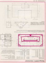
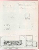
Time to get some images up here, this is all getting a bit to abstract without something to look at!
Have scanned the construction drawings from the original magazines.
Resolution is a bit poor due to file size restriction, but if anybody would like the the full quality scans, just let me know and I'll @-mail them!
Attachments
Well, here we go!
Bought some MDF today and started cutting out bits and pieces, the RT-2 horn is under way!
I've decided to go for this design as it was originally designed by some fairly knowledgeable guys, and I doubt that I'm capable of coming up with a better design.
One thing is to run theoretically correct sims with Hornresp, realising a working design is seemingly another issue altogether..
So now it's back to that driver selection....
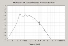
The Eminence Kappa Pro 12 seems to have all the right things, relatively low Fs, low Qts, high BL, and a relatively low Mms, in particular considering that it is a pro-driver with low Fs.
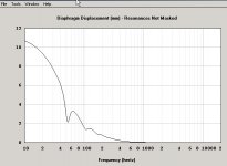
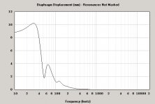
When I use this in the Hornresp Model, the SPL curve looks fairly OK, but cone excursion seems exceed Xmax below 45 Hz. As the Kappa's have a fairly ample maximum Excursion (Xlim) of 14.8 mm, they should still have a good chance of survival.
Another driver I'm considering, and very different to the Kappa's, s the peerless sls 315.
A typical HI-FI subwoofer driver, this seems to differ from the Kappa's in that it will give a much smoother response and a cone excursion inside its Xmax (which is greater than that of the kappa's), when the rear closed chamber is somewhat reduced sin size.
The peerless also displays lower peak impedance, bot in frequency and magnitude, and the efficiency is somewhat lower than for the Kappa's. The heavier cone-weight also becomes apparent through a lower roll-off point for the higher frequencies.
I'm tempted to go for the Peerless driver due to the smoother frequency response and the fact that more of its cone excursion takes place within Xmax. Still, I'm uncertain that there are some trade-offs to this which I am unable to understand or extract from the Hornresp simulations...
Which driver should I go for???
Enclosed is the SPL curve with with the Kappa's @ 20 v
Bought some MDF today and started cutting out bits and pieces, the RT-2 horn is under way!
I've decided to go for this design as it was originally designed by some fairly knowledgeable guys, and I doubt that I'm capable of coming up with a better design.
One thing is to run theoretically correct sims with Hornresp, realising a working design is seemingly another issue altogether..
So now it's back to that driver selection....
The Eminence Kappa Pro 12 seems to have all the right things, relatively low Fs, low Qts, high BL, and a relatively low Mms, in particular considering that it is a pro-driver with low Fs.
When I use this in the Hornresp Model, the SPL curve looks fairly OK, but cone excursion seems exceed Xmax below 45 Hz. As the Kappa's have a fairly ample maximum Excursion (Xlim) of 14.8 mm, they should still have a good chance of survival.
Another driver I'm considering, and very different to the Kappa's, s the peerless sls 315.
A typical HI-FI subwoofer driver, this seems to differ from the Kappa's in that it will give a much smoother response and a cone excursion inside its Xmax (which is greater than that of the kappa's), when the rear closed chamber is somewhat reduced sin size.
The peerless also displays lower peak impedance, bot in frequency and magnitude, and the efficiency is somewhat lower than for the Kappa's. The heavier cone-weight also becomes apparent through a lower roll-off point for the higher frequencies.
I'm tempted to go for the Peerless driver due to the smoother frequency response and the fact that more of its cone excursion takes place within Xmax. Still, I'm uncertain that there are some trade-offs to this which I am unable to understand or extract from the Hornresp simulations...
Which driver should I go for???
Enclosed is the SPL curve with with the Kappa's @ 20 v
Attachments
Elbert said:
But then again, if I change the horn lenght, say +/-5 cm, I don't expect that to have any radical impact on the outcome.
But this sort of goes against the grain where High BL/ Low Qts pro-like drivers are supposedly the ideal choice for horn applications ... ?
I have read that the driver Fs should be lower than the cut-off of the horn. Could this explain something as the HI-fi drivers had Fs in the 20 Hz range?
In the scheme of things, not really, but so many folks are anal about such things, so I feel I should give as technically correct answers as I can and let folks do whatever they want with the info.
The rule-of-thumb that a horn driver must have a low Mms harks back to the day when matching impedance amps were the rule, which doubles Qes, cutting the effective motor strength in half, so proportionately, a low Mms effectively becomes a high one in the speaker system, ergo the horn needs to be designed based on this Vs its raw specs. This is why when speakers designed this way are driven with a vanishingly low output impedance SS amp they sound horrible with a very forward mids and rolled off, flabby bass line as well as a muted HF.
Anyway, like any speaker design we want the right specs for the BW, so for a bass horn we need a low mass corner, i.e. in your case a ~150 Hz one and since the driver's Fs needs to be above the flare frequency to keep the compression chamber small and compression ratio reasonable, a ~42 Hz Fs, ~0.56 Qes in a compression chamber suitable for its Vas is one 30 hz solution, but this horn's throat is way too big for a 150 Hz BW compression horn, so these specs in theory won't work well even if series resistance is used to increase the similar Fs 2202H's Qes, Qts.
That said, adding ~3 ohms series resistance will flatten it out somewhat to 150 Hz and fill up the large compression chamber. If SS power and sufficiently large gauge wire to keep series resistance <0.1 ohm is used, then based on an effective ~28.2 Hz long acoustic path-length, reducing its compression chamber Vb to ~12.4 L to ~reactance annul it to severely reduce its excursion seems a good plan.
Anyway, since I can't get even close to its measured response no matter what combination of acoustic path-length, series resistance and compression chamber Vb/stuffing density I tried I have no faith in any sims with any drivers as it now stands, so caveat emptor.
GM
GM,
Thanks for a very comprehensive and informative answer!
First of all, today I realized that I made an error with the model..
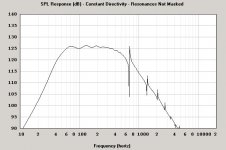
The horn starts off with a opening of 570 cm2, but just after the horn entry, the area narrows down to 393 cm2 before it starts to expand again! I've approximated this first section to be about 10 cm long, leaving the rest of the horn to be approx. 206 cm long..
In the enclosed image, you can see the new response, with the first JBL 2202 response in grey.
As can be seen, the response is now slightly smoother, but as you point out, the resemblance to the original measurements is still not quite there...
Apart from a directly faulty model or the original test-setup, the only other unknown i can come up with is the 17.8 L volume made up by the triangular foot of the horn. This horn has a slot-like connection with the main compression chamber of the horn. Could this perhaps act as a Helmholtz resonator or something??
Anyway, I agree that the model I've made probably leaves something to be desired in terms of replicating the actual design..
I can only hope that it has some use for making relative comparisons between various drivers..
Regarding Mms, I must admit I have no clue what a Matching Impedance amp is.. I intend to use a modern high performance mosfet amp and heavy gauge wires.
In the original magazine article, the horn was designed for a Hokutone W300F08 woofer cited to have a moving mass of 23g. The other drivers tested that yielded good results were also drivers with "light cones". It was also to be read that woofers with "heavy cones" (no data provided) were cited to have a less distinct and more colored sound.
It was however stated that the unsuitable heavy cone woofers were "typical" sealed enclosure woofers, but that such wooferscould perhaps be used if the volume was reduced by blanking of the cavity in the foot.
As i Have no data for these elements, I can perhaps assume that their lacking performance was due to the amplifier issue you mentioned and/ or very heavy cones combined with a magnet system which is somewhat feeble by todays standards.. (?)
I tried to do some simualtions with significantly reduced volume of the rear chamber to bring the cone excursion down, but in order to have a significant effect, the bass extension seemed to suffer considerably.
Both the Kappa and the Peerless do however seem to have a resonance above 30 Hz in this system, at 37 and 35 Hz respectively (peak impedance), so both drivers should survive realistic listening levels without reducing the cavity volume further. An electronic 30-35 Hz High-pass filter should reduce the most severe excursions and reduce distortion as well..
Well Caveat emptor it is, and I think I'll go for the kappa..
It seems the Peerless might have an advantage in low frequency extension, but the kappa gives much greater efficiency which should give for less distortion and less power compression..
Thanks for a very comprehensive and informative answer!
First of all, today I realized that I made an error with the model..
The horn starts off with a opening of 570 cm2, but just after the horn entry, the area narrows down to 393 cm2 before it starts to expand again! I've approximated this first section to be about 10 cm long, leaving the rest of the horn to be approx. 206 cm long..
In the enclosed image, you can see the new response, with the first JBL 2202 response in grey.
As can be seen, the response is now slightly smoother, but as you point out, the resemblance to the original measurements is still not quite there...
Apart from a directly faulty model or the original test-setup, the only other unknown i can come up with is the 17.8 L volume made up by the triangular foot of the horn. This horn has a slot-like connection with the main compression chamber of the horn. Could this perhaps act as a Helmholtz resonator or something??
Anyway, I agree that the model I've made probably leaves something to be desired in terms of replicating the actual design..
I can only hope that it has some use for making relative comparisons between various drivers..
Regarding Mms, I must admit I have no clue what a Matching Impedance amp is.. I intend to use a modern high performance mosfet amp and heavy gauge wires.
In the original magazine article, the horn was designed for a Hokutone W300F08 woofer cited to have a moving mass of 23g. The other drivers tested that yielded good results were also drivers with "light cones". It was also to be read that woofers with "heavy cones" (no data provided) were cited to have a less distinct and more colored sound.
It was however stated that the unsuitable heavy cone woofers were "typical" sealed enclosure woofers, but that such wooferscould perhaps be used if the volume was reduced by blanking of the cavity in the foot.
As i Have no data for these elements, I can perhaps assume that their lacking performance was due to the amplifier issue you mentioned and/ or very heavy cones combined with a magnet system which is somewhat feeble by todays standards.. (?)
I tried to do some simualtions with significantly reduced volume of the rear chamber to bring the cone excursion down, but in order to have a significant effect, the bass extension seemed to suffer considerably.
Both the Kappa and the Peerless do however seem to have a resonance above 30 Hz in this system, at 37 and 35 Hz respectively (peak impedance), so both drivers should survive realistic listening levels without reducing the cavity volume further. An electronic 30-35 Hz High-pass filter should reduce the most severe excursions and reduce distortion as well..
Well Caveat emptor it is, and I think I'll go for the kappa..
It seems the Peerless might have an advantage in low frequency extension, but the kappa gives much greater efficiency which should give for less distortion and less power compression..
Attachments
And when I had just about made up my mind...
Just stumbled across a driver called Gamma LA 1231...
http://www.hifikit.se/index.php?id=144
This is apparently a new version of an older driver that was popular back in the 70's, and also recommended for a lot of the RT-horns back then..
Data was a bit sparse, but I managed to get most of it, exept for Qms.
I did however vary the Qms input between "typical" values (1,5-4), then settling for 2.5. Varying between 1,5 to 4 didn't really change the response curve that much.
What characterizes this woofer, is a very low Fs of 25 Hz and a very low Moving mass (Mmd) of only 19 g!
So, a typical "light cone" driver as often described in the original RT-horn articles...
What response will this sort of woofer given in a simulation??
A very flat one it seems, Perhaps a better choice than the eminence Kappa pro after all??
Attachments
Elbert said:could send you a scan of the cutting-list and build plan if U're interested.
i'd love to see it. thanks.
Re: Re: Bass horn driver?
got any plans for this? totally cool!
Jmmlc said:Hello,
There is often a solution for bass horn that is still WAF.
In the attached picture you'll see the (Le Cléac'h) bass horn built by my friend Frédéric Lebas.
Best regards from Paris, France
Jean-Michel Le Cléac'h
got any plans for this? totally cool!
- Status
- This old topic is closed. If you want to reopen this topic, contact a moderator using the "Report Post" button.
- Home
- Loudspeakers
- Multi-Way
- Bass horn driver?