Just wanted to post this up, there's obviously big differences between the data Zaph got for the SB Acoustics 6" driver and the published data sheet. I have a couple pair here that I just got from Madisound, and was modeling up a box tonight. The data below is with a totally fresh driver, no break-in at all. I used a WT2 and Delta Mass method for Vas testing.
Here's what I got, that's more like it! I gotta wonder if the unit Zaph had was defective, the 1.17 Le makes me wonder. I could post a pic of the Inductance curve from the WT2, but it's damn near ruler flat out to 20khz ... even lower than Scan Revelators I've tested.
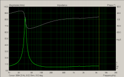
No FR or distortion data to post yet, but there was a prominent phase wiggle at 1500hz, so there likely is a cone/surround resonance there as shown on Zaphs data at the factory spec sheet.
Re = 5.5880 ohms
Fs = 39.3941 Hz
Zmax = 50.9692 ohms
Qes = 0.5213
Qms = 4.2336
Qts = 0.4641
Le = 0.1740 mH (at 1 kHz)
Diam = 122.5734 mm ( 4.8257 in )
Sd =11800.0004 mm^2( 18.2900 in^2)
Vas = 23.1003 L ( 0.8158 ft^3)
BL = 6.0895 N/A
Mms = 13.9762 g
Cms = 1167.8557 uM/N
Kms = 856.2701 N/M
Rms = 0.8171 R mechanical
Efficiency = 0.2546 %
Sensitivity= 86.0757 dB @1W/1m
Sensitivity= 87.6340 dB @2.83Vrms/1m
Here's what I got, that's more like it! I gotta wonder if the unit Zaph had was defective, the 1.17 Le makes me wonder. I could post a pic of the Inductance curve from the WT2, but it's damn near ruler flat out to 20khz ... even lower than Scan Revelators I've tested.
No FR or distortion data to post yet, but there was a prominent phase wiggle at 1500hz, so there likely is a cone/surround resonance there as shown on Zaphs data at the factory spec sheet.
Re = 5.5880 ohms
Fs = 39.3941 Hz
Zmax = 50.9692 ohms
Qes = 0.5213
Qms = 4.2336
Qts = 0.4641
Le = 0.1740 mH (at 1 kHz)
Diam = 122.5734 mm ( 4.8257 in )
Sd =11800.0004 mm^2( 18.2900 in^2)
Vas = 23.1003 L ( 0.8158 ft^3)
BL = 6.0895 N/A
Mms = 13.9762 g
Cms = 1167.8557 uM/N
Kms = 856.2701 N/M
Rms = 0.8171 R mechanical
Efficiency = 0.2546 %
Sensitivity= 86.0757 dB @1W/1m
Sensitivity= 87.6340 dB @2.83Vrms/1m
I have a broken in pair and got 0.96mH inductance, but I'm not sure if it is correct. I'm using LIMP for measurements and I remember getting two conflicting values for Le. The value changes if I copy the T/S data to clipboard (using the button in the program's window).
It just so happens to be that I'm now building a small box to help with impedance measurements. I will take new results later today and post the results.
It just so happens to be that I'm now building a small box to help with impedance measurements. I will take new results later today and post the results.
Hi
Using delta mass (16.8 grams worth of coins) the following parameters were estimated with LIMP (part of ARTA software package):
Woofer #1:
Fs = 31.49 Hz
Re = 5.40 ohms[dc]
Le = 976.38 uH
L2 = 501.94 uH
R2 = 1.98 ohms
Qt = 0.40
Qes = 0.42
Qms = 6.78
Mms = 13.44 grams
Rms = 0.392489 kg/s
Cms = 0.001900 m/N
Vas = 36.46 liters
Sd= 116.90 cm^2
Bl = 5.816173 Tm
ETA = 0.26 %
Lp(2.83V/1m) = 87.93 dB
Woofer #2:
Fs = 31.83 Hz
Re = 5.40 ohms[dc]
Le = 1116.50 uH
L2 = 493.30 uH
R2 = 2.05 ohms
Qt = 0.41
Qes = 0.43
Qms = 7.34
Mms = 15.36 grams
Rms = 0.418130 kg/s
Cms = 0.001628 m/N
Vas = 31.25 liters
Sd= 116.90 cm^2
Bl = 6.175771 Tm
ETA = 0.22 %
Lp(2.83V/1m) = 87.29 dB
The woofers have been broken in using high excursion sine for 50h+. No guarantees about accuracy!
Attachments
Looking at Zaph's results in his 6.5" group there is really not a lot of diiference with your results Turbo. Am I missing something?
He's showing .45 mh for Le opposed to your .17 mh, but those values come from different methods. Yours is at 1khz while Zaph's is done using curve fitting over a range frequencies. Both can have their inaccuracies (especially with full copper sleeves on pole pieces), so looking at the actual impedance gives a better idea of what is going on.
Too bad they have such a good motor on a cone/surround with that breakup problem...Have you used this yet Turbo?
Hi,
I have ordered some of the 5" and doing a projekt. Right now im waitting for the enclosures to be finished.
the enclosure drawing can be seen here.
http://www.hifi4all.dk/forum/forum_posts.asp?TID=67715
later, ill add it to my website.
I have ordered some of the 5" and doing a projekt. Right now im waitting for the enclosures to be finished.
the enclosure drawing can be seen here.
http://www.hifi4all.dk/forum/forum_posts.asp?TID=67715
later, ill add it to my website.
A coil sitting in an air gap surrounded by iron does not behave like a true inductor - far from. As a consequence of eddy-current losses, it behaves more like a semi-inductor. Therefore you CANNOT use an LCR-meter to measure loudspeaker voice coil inductance - an certainly not if the coil has been removed from the air gap. In the case of the SB driver, there is a copper cap on the pole piece, which also conducts eddy-currents and significantly reduces the (apparent) inductance.
Loudspeaker voice coil inductance (in Henry) is calculated by an empiric equation:
Le = ((Re*20000/(2*pi*f3))+0.5)/20000
, where f3 is the frequency at which the impedance (i.e. modulus) is 3 dB (i.e. a factor sqrt 2 ) higher than Zmin (the minimum impedance above resonance).
This is considered to be the best single inductor approximation/representation, though it is a poor model, which I never use myself.
The hump on the impedance curve is always to be expected when using a low damping surround. Look at the Scan-Speak 18W/8531 for instance. You can easily get rid of the hump by using a high damping surround (material) - that is if you can live with the loss of dynamics and transparency (I can't).
I just took a closer look at the (enlarged) impedance curve for the 6" driver shown on SB Acoustics web-site.
The impedance axis shows 6.6666666..... ohm/div
I determine Zmin to be 6.6 ohm, so f3 has to be found at 9.3 ohm - and that is at just about 7 kHz.
I calculate Le = 0.15 mH
It looks like they are right (assuming Re = 5.7 ohm).
Measuring Re accurately is not trivial, as common values of Re are to be considered low. Most mulit-meters will actually NOT do the job properly. If you ARE using a multi-meter, at least measure the wire resistance by holding the ends of the test wires together. Subtract this value from your measurement result. The best thing to do, however, is to use a 4-wire ohm-meter (quite expensive though). Also remember to compensate for the ambient temperature. Datasheet values of Re usually apply for 20 °C (68 F) - voice coil temperature.
Finally, there is a tolerance on everything. I know for a fact that Scan-Speak has a tolerance on Re, which is ±0.15 ohm or ±2% (larger value applies).
This driver has excellent nonlinear distortion performance according to Zaph's test. I have a new 2-way design using this driver with the Vifa DQ25SC tweeter:
http://www.geocities.com/woove99/Spkrbldg/jays_blog.htm
Currently two people are building this design. It will replace my Dayton RS180/Seas 27TDFC 2-way.
-jAy
http://www.geocities.com/woove99/Spkrbldg/jays_blog.htm
Currently two people are building this design. It will replace my Dayton RS180/Seas 27TDFC 2-way.
-jAy
Finished my own project with Seas DXT tweeter. Active crossover (FIR filter with minimum phase response linearization and linear phase xo).
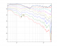
Woofer raw response in box, 220x400 (WxH), 20 mm roundover. A resonance can be seen in the 1.5 KHz range, it fudges with the directivity and was the primary reason for adapting a 1550 Hz crossover point in the "finished" work.
Woofer raw response in box, 220x400 (WxH), 20 mm roundover. A resonance can be seen in the 1.5 KHz range, it fudges with the directivity and was the primary reason for adapting a 1550 Hz crossover point in the "finished" work.
Attachments
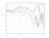
Final response with tweeter. Measurements are 0-90 degrees horizontal. No smoothing applied, but real frequency resolution is coarse due to short time window (~3 ms). Graphs show more apparent resolution due to longer FFT length (zero padded).
2-3 KHz on-axis shows baffle diffraction effects. It is unfortunate, but in the big picture the dip is not very deep. Preferred listening axis 20 degrees.
2-3 KHz on-axis shows baffle diffraction effects. It is unfortunate, but in the big picture the dip is not very deep. Preferred listening axis 20 degrees.
Attachments
I'm working on a 2-way, SB 7" woofer and the SB tweeter. Currently using SoundEasy in DF mode for auditioning. The tweeter is "tweaked" to smooth out the response, at the expense of peaking the low end. When combined with baffle placement taking diffraction into account, it's not too difficult to work with.
I don't see the 1.5K resonance in my measurements of the woofer in-box @1m, but it does appear on my 2mx2m baffle measurements @0.5m. Must be the window setting differences.
The issue I see with the SB17 is the low sensitivity. I've selected a system sensitivity of 83db to get reasonable bass extension, but I'm stand mounting them as well. I also wouldn't think that anyone would expect too much from these in the way of SPL, they are just a small 2-way. It will be interesting to see just how much these can be pushed.
I've been pleasantly surprised at the overall sound so far. Very open with good balance and surprising imaging. The latter is where the tweeter tweak is important. I measured a fair difference between the two tweeters without it.
The crossover is not too complicated. Using inexpensive drivers, a costly crossover is a bit counter-productive, but my intent is to see just how much I can get out of these with a bit more than a minimal crossover.
They are in a closed box for now, but I'll also be changing to the a reflex setup as well to see which one is better overall. My comparisons are going to be a SS 15W/Morel MDT-44 and an older Seas 17W/T25CF-001.
At this point, I like these drivers within their limitations.
Dave
- Status
- This old topic is closed. If you want to reopen this topic, contact a moderator using the "Report Post" button.
- Home
- Loudspeakers
- Multi-Way
- SB Acoustics 6" Params