Hello, I may require a small system soon for a fairly low cost and obviously DIY came into mind! As an overview, I need it to sound decent for music, films, games etc, it will be used with a PC in a bedroom size room. Many systems like this exist commercially but most look to have pretty terrible performance.
I intend to use a pair of Hi-Vi B3N's for the sats. These are quite well regarded, are cheap and available plus look pretty cool . These will be in a sealed box, it needs to be small so I am working with 1.6L. This causes a bit of a hump but with the crossover applied it isn't very serious. Dimensions will be quite tall and slim to save desk space and stop driver being so near desk/so off axis. W-96mm, H-365mm, D-89mm.
The "sub" will be a Hi-Vi M3a in a ported box, 28L, 35Hz tuning (as reccomended by manufacturer in fact). This will be shaped a bit like the BOSE subseek: ) with rough dimensions W-225mm, H365-mm, D-433mm. A slot type port will likely be employed. The driver is relatively cheap and looks well made, obviously matches B3Ns aesthetically too
The crossover I plan to use 6th order 36db on the sub and 4th order 24db on the satellites, this keeps the changeover more natural as there is already 12db rolloff inherent in the small sealed satellites. Steep orders appear to produce better changeover and with it being quite high (120hz) on the sub will hopefully reduce the localisation
effects. Also keeps the little B3N's happy with the 24db rolloff
The crossovers will naturally be active and BSC + notch filters will also be included in the satellites chain to tailer the response.
Here are some FR graphs:
I am also looking at using all pass filters to improve the phase response between the sub and satellites. I don't know how relevant it is at these frequencies and with the sub positioned on the floor? If it could help integrate the sub and sats better then I'd need some help figuring out how to make the physical all pass filter that I have modelled in ISD Pro (part values etc).
Here is the phase response with the all pass bringing the phases together at crossover frequency:
and here without the all pass:
Would it help in practise?
Proposed amplifiers are these:
http://www.maplin.co.uk/Module.aspx?TabID=1&ModuleNo=5292&doy=25m8
Two modules needed. One bridged to power the sub, the other used at 2 channel amp for the sats. I'm sure they arn't great but am working to as small a budget as possible! Open to suggestions on this but nothing too complicated if possible, all the op-amps will already be problem enough .
Suggestions/comments? Sorry for long post!
I intend to use a pair of Hi-Vi B3N's for the sats. These are quite well regarded, are cheap and available plus look pretty cool
. These will be in a sealed box, it needs to be small so I am working with 1.6L. This causes a bit of a hump but with the crossover applied it isn't very serious. Dimensions will be quite tall and slim to save desk space and stop driver being so near desk/so off axis. W-96mm, H-365mm, D-89mm.The "sub" will be a Hi-Vi M3a in a ported box, 28L, 35Hz tuning (as reccomended by manufacturer in fact). This will be shaped a bit like the BOSE subs
eek: ) with rough dimensions W-225mm, H365-mm, D-433mm. A slot type port will likely be employed. The driver is relatively cheap and looks well made, obviously matches B3Ns aesthetically too The crossover I plan to use 6th order 36db on the sub and 4th order 24db on the satellites, this keeps the changeover more natural as there is already 12db rolloff inherent in the small sealed satellites. Steep orders appear to produce better changeover and with it being quite high (120hz) on the sub will hopefully reduce the localisation
effects. Also keeps the little B3N's happy with the 24db rolloff
The crossovers will naturally be active and BSC + notch filters will also be included in the satellites chain to tailer the response.
Here are some FR graphs:
An externally hosted image should be here but it was not working when we last tested it.
I am also looking at using all pass filters to improve the phase response between the sub and satellites. I don't know how relevant it is at these frequencies and with the sub positioned on the floor? If it could help integrate the sub and sats better then I'd need some help figuring out how to make the physical all pass filter that I have modelled in ISD Pro (part values etc).
Here is the phase response with the all pass bringing the phases together at crossover frequency:
An externally hosted image should be here but it was not working when we last tested it.
and here without the all pass:
An externally hosted image should be here but it was not working when we last tested it.
Would it help in practise?
Proposed amplifiers are these:
http://www.maplin.co.uk/Module.aspx?TabID=1&ModuleNo=5292&doy=25m8
Two modules needed. One bridged to power the sub, the other used at 2 channel amp for the sats. I'm sure they arn't great but am working to as small a budget as possible! Open to suggestions on this but nothing too complicated if possible, all the op-amps will already be problem enough
. Suggestions/comments? Sorry for long post!
Neat little project. I'd be tempted to first try a 4th-order Linkwitz-Riley crossover which will have pleasant phase characteristics. The sub is easy just needs a textbook filter, but the satellite you can use the acoustic output to match with a tuned 2nd-order filter to make a true acoustic 4th-order with the right Q. You just need to know Fc and Qtc which are quite easy to measure.
At the moment I don't think you are properly taking the acoustic response into account, just doing a rough implementation considering filter order but not Q.
As to if higher order is better, well lower order can give a more natural sound, it depends on if you notice localisation or steep roll-off. Everybody is different.
If it helps I have layouts for filter PCBs on my website www.readresearch.co.uk also filter calculators.
Thanks for the reply! Can't say I understand fully the effect of Q but I had another play around with it to see what I could do. Arrived at a filter Q of 0.555 pretty experimentally by what line looked straightest with the frequency set for 113.1Hz (the box Fsc). Box Q was 1.17 for the satellite but I don't know how that fits in? Anything like 1.17 minus 0.707 (the ideal/desired Q) to arrive at 0.463? Line didn't look so "good" like this though
I set the 4th order sub filter to try and meet the satellite at the -6db point on the graph. No idea if thats right, I think the LR filter should be 6db down at the set frequency? Then again, the sub has a hump to its response of about 1db at its worst (65hz).
My results so far...
I set the 4th order sub filter to try and meet the satellite at the -6db point on the graph. No idea if thats right, I think the LR filter should be 6db down at the set frequency? Then again, the sub has a hump to its response of about 1db at its worst (65hz).
My results so far...
An externally hosted image should be here but it was not working when we last tested it.
Not far off. The Q multiplies, so if your satellite Q is 1.17 you need a 2nd-order filter Q of 0.5/1.17=0.427. Set Fo of the filter to Fc of the satellite. This acoustic combination should be -6dB at this frequency and is your crossover frequency.
Linkwitz-Riley Q is 0.5. To make the sub filter it's just 2 cascaded Butterworth 2nd-order filters with Fo at the crossover frequency.
Linkwitz-Riley Q is 0.5. To make the sub filter it's just 2 cascaded Butterworth 2nd-order filters with Fo at the crossover frequency.
Ok, trying that this is what I get:
Which looked wrong to me because of the droop in the satellites response down toward the crossover, but then again mabye the sub will account for this and fill it back out again? Pity I can't see the summed response. The -6db point is correct now though at around 113Hz. The little B3N seems to cope alright with the 12db filter, never exceeding its X-max with the available power, though at 2mm it might be quite high in distortion. Don't know how you'd implement this with 36db and 24db slopes now though.
An externally hosted image should be here but it was not working when we last tested it.
Which looked wrong to me because of the droop in the satellites response down toward the crossover, but then again mabye the sub will account for this and fill it back out again? Pity I can't see the summed response. The -6db point is correct now though at around 113Hz. The little B3N seems to cope alright with the 12db filter, never exceeding its X-max with the available power, though at 2mm it might be quite high in distortion. Don't know how you'd implement this with 36db and 24db slopes now though.
I think the sub low end response may be skewing the low-pass because they are close together. You chould check this by making the box extend down to 1Hz or something, then the crossover should look better.
If this is the case then this is where it gets difficult. I think you need to adjust the low-pass to give you an acoustic 4th-order Linkwitz-Riley, taking the sub box induced high-pass into account. Show use a graph of the sub without low-pass on.
If this is the case then this is where it gets difficult. I think you need to adjust the low-pass to give you an acoustic 4th-order Linkwitz-Riley, taking the sub box induced high-pass into account. Show use a graph of the sub without low-pass on.
Ok, I see what you mean. The bass response looks like a hill and there is no flat range? Here is the reponse without the lowpass:
The main problem I had was the satellite having this droop in its lower end when using the updated filter Q. Is this normal? Does it actually cause a problem or does the sub fill it out?
An externally hosted image should be here but it was not working when we last tested it.
The main problem I had was the satellite having this droop in its lower end when using the updated filter Q. Is this normal? Does it actually cause a problem or does the sub fill it out?
When the sub is crossed over with the matching acoustic 4th-order Linkwitz-Riley response it will sum flat. As you have seen looking at the unfiltered sub response the response is not flat in the region where you want to cross over, so it's skewing the textbook response. Unfortunately working out the appropriate filter is not as simple as with the satellite. It involves trial and error. The problem is compounded by the humped sub response.
Maybe start by lowering the sub filter Q.
Maybe start by lowering the sub filter Q.
Thanks again for your help!
I think this is something like it. I couldn't do a single 4th order so had to use two 2nd order to achieve this. I simply played with the Q factor so as to make the hump dissapear and maximal level be at 0db. I don't know if it's relevant but raising the crossover frequency makes the hump re-appear.
I think this is something like it. I couldn't do a single 4th order so had to use two 2nd order to achieve this. I simply played with the Q factor so as to make the hump dissapear and maximal level be at 0db. I don't know if it's relevant but raising the crossover frequency makes the hump re-appear.
An externally hosted image should be here but it was not working when we last tested it.
Hmm, this produces a nicer looking response. Lower Q but moved the crossover frequency up too; don't know if thats a good idea  . I did it to centre the -6db point of the sub at the same 113Hz as the satellite, while keeping the hump under control (has a small flat area now too in the sub response).
Lowering the sub cutoff reduces the hump by nature but I think I must cross at the 113Hz of the satellite (or as I have here 117.8Hz).
. I did it to centre the -6db point of the sub at the same 113Hz as the satellite, while keeping the hump under control (has a small flat area now too in the sub response). Lowering the sub cutoff reduces the hump by nature but I think I must cross at the 113Hz of the satellite (or as I have here 117.8Hz).
An externally hosted image should be here but it was not working when we last tested it.
Yes the 6dB point is where to cross to with a mirror image of the high-pass curve, to have the Linkwitz-Riley response.
It may take some time to get it right, if you can at all. One of the beautys of going active is that you can build it now and listen and if you decide to tweak it later it's just a matter of swapping about £1 worth of resistors and/or capacitors.
It may take some time to get it right, if you can at all. One of the beautys of going active is that you can build it now and listen and if you decide to tweak it later it's just a matter of swapping about £1 worth of resistors and/or capacitors.
Ok, it sounds like the specs on the B3Ns may not be that accurate so i'll probably have to do some experimenting/measuring anyhow. Assuming that latest crossover is a good starting point how would I actually go about making it? Where can I find the schematic of this custom filter with equations to calculate Q?
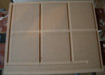
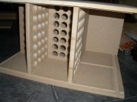
A quick question on the sub too since I'd like to start cutting wood today for it. Can the port be done as per image 1 (where the bottom part of the enclosure forms one side of the slot port) or must it be done as per image 2 with two free edges?
A quick question on the sub too since I'd like to start cutting wood today for it. Can the port be done as per image 1 (where the bottom part of the enclosure forms one side of the slot port) or must it be done as per image 2 with two free edges?
Attachments
Cool, looks like there is indeed lots of useful stuff on there
I had already worked out my box dimensions in WIN ISD however, just wanted to check that port would be ok. Here's todays progress, I expect you can see where its going . Only 12mm MDF but you can see that quite extensive bracing will be used along with a double thickness (possibly MDF and Ply) baffle. Have to make another just like this tomorrow though. Oh well, at least it's only 1 sub
I had already worked out my box dimensions in WIN ISD however, just wanted to check that port would be ok. Here's todays progress, I expect you can see where its going
. Only 12mm MDF but you can see that quite extensive bracing will be used along with a double thickness (possibly MDF and Ply) baffle. Have to make another just like this tomorrow though. Oh well, at least it's only 1 sub Attachments
Just as a bit of an update . The photo shows a trial assembly, both "side" panels have the routed grooves into which the bracing, inner baffle, port and outer panels fit; so these parts are just slotted together for this test.
I still need to drill more holes , but once thats done I'll add up the actual volume and cut the port to the correct length. I know the volume is less than I wanted (didn't exclude port volume ) so I'll need to make the port narrower, probably in the sides so it won't reach the edges of the box. Sill achieves a -3db point at 39hz so not too bad for its compact size, the hump isn't too drastic either
. The photo shows a trial assembly, both "side" panels have the routed grooves into which the bracing, inner baffle, port and outer panels fit; so these parts are just slotted together for this test. I still need to drill more holes
, but once thats done I'll add up the actual volume and cut the port to the correct length. I know the volume is less than I wanted (didn't exclude port volume ) so I'll need to make the port narrower, probably in the sides so it won't reach the edges of the box. Sill achieves a -3db point at 39hz so not too bad for its compact size, the hump isn't too drastic either Attachments
Dr EM,
the Hivi B3N & B3S are very similar and I built this design here.
What I can tell you is that without a tweeter, these drivers are very directional when it comes to the higher frequencies. I love the results I got but I really have to have the speakers pointed at my head to hear any highs. I would strogly suggest you get a design with a tweeter to avoid this problem unless you don't mind a very small listening window.
Good luck,
Peter
Thanks for your input! I have a Monacor SPH-30X which is also a 3" full-ranger and the treble does diminish off axis. I hope in my application it won't be too much of an issue since it'll be used whilst sat at the desk mainly. What I'll do is make sure the B3Ns are well up from the desk and posistioned as close to sitting ear height as possible. It is unfortunate I won't be able to move around and listen elsewhere in the room but adding even basic tweeters will up the budget a lot once crossover and L-pads are added in along with postage on the tweeters. Will try and leave room for some just in case though
Started glueing on the sub box today, will update with pics tomorrow. Shouldn't take too much longer I hope, waiting for the driver at the moment though. Those braces ended up with a total of 136 holes , glad thats done
Started glueing on the sub box today, will update with pics tomorrow. Shouldn't take too much longer I hope, waiting for the driver at the moment though. Those braces ended up with a total of 136 holes
, glad thats done Said I'd update you so here we go:
Just got to sort out the double thick baffle and the brace that sits behind it
The port has been divided into 2 smaller ones. This looked like the best solution to adjusting the port size down as it adds physical bracing and apparently halves the port turbulence (perhaps its the value for each?).
Also rather nicely my drivers turned up yesterday. I was rather impressed with the little M8a when I tested it. Really quiet excursion, heres a video if your interested:
http://www.youtube.com/watch?v=xBhDC6fYI6Q
The B3N sounds good too, using some music software to roughly apply the intended filters. Really clear on most things though struggles on more complicated parts, kind of as expected.
An externally hosted image should be here but it was not working when we last tested it.
Just got to sort out the double thick baffle and the brace that sits behind it
The port has been divided into 2 smaller ones. This looked like the best solution to adjusting the port size down as it adds physical bracing and apparently halves the port turbulence (perhaps its the value for each?).
Also rather nicely my drivers turned up yesterday. I was rather impressed with the little M8a when I tested it. Really quiet excursion, heres a video if your interested:
http://www.youtube.com/watch?v=xBhDC6fYI6Q
The B3N sounds good too, using some music software to roughly apply the intended filters. Really clear on most things though struggles on more complicated parts, kind of as expected.
- Status
- This old topic is closed. If you want to reopen this topic, contact a moderator using the "Report Post" button.
- Home
- Loudspeakers
- Multi-Way
- Sub sat system design