I'm building a conical midbass horn loaded with an GPA 515G driver. It's based off of Erik's work at
http://www.volvotreter.de/pics/conical_horn_setup_06.jpg
Going from the Hornsrep data to the build plan should be pretty straight forward except for this one angle "C". For the time being forget about getting the mouth and throat flush, I can calculate those angles.
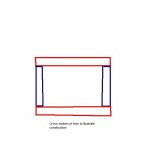
For my construction (see first picture), the top and bottom walls (horizontal planes) of the horn are going to be somewhat simple wedges, but it's the sidewalls which will need to be cut at an angle to insure all walls of the horn are at 90 deg when taking a cross section.
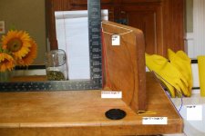
In the second picture we're looking at a mock up of the horn from the listening position. The white note pad represents the horn throat and the lens cap is sitting in the horn mouth. The two cutting boards represent the walls of the horn. As you can see, if I cut the sidewalls of the horn at 90 deg, the horn cross section will not be square.
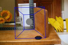
The black "square" is sitting there to represent the required square cross section. As you can see, if angle "C" is a simple 90 degs like the breadboard it will come out all wrong. It must be cut at unknown angle "C". Any ideas?
http://www.volvotreter.de/pics/conical_horn_setup_06.jpg
Going from the Hornsrep data to the build plan should be pretty straight forward except for this one angle "C". For the time being forget about getting the mouth and throat flush, I can calculate those angles.
For my construction (see first picture), the top and bottom walls (horizontal planes) of the horn are going to be somewhat simple wedges, but it's the sidewalls which will need to be cut at an angle to insure all walls of the horn are at 90 deg when taking a cross section.
In the second picture we're looking at a mock up of the horn from the listening position. The white note pad represents the horn throat and the lens cap is sitting in the horn mouth. The two cutting boards represent the walls of the horn. As you can see, if I cut the sidewalls of the horn at 90 deg, the horn cross section will not be square.
The black "square" is sitting there to represent the required square cross section. As you can see, if angle "C" is a simple 90 degs like the breadboard it will come out all wrong. It must be cut at unknown angle "C". Any ideas?
Attachments
Maybe a sketch would help, I am not sure how picture 2 relates to the project you reference.
You need three things for a square conical flare, right?
What is the mouth area?
What is the throat area?
What is the length?
From those I think we/you should be able to figure out the rest. You are doing it with butt joints, it appears, which is easier.
You need three things for a square conical flare, right?
What is the mouth area?
What is the throat area?
What is the length?
From those I think we/you should be able to figure out the rest. You are doing it with butt joints, it appears, which is easier.
As you can see, if angle "C" is a simple 90 degs like the breadboard it will come out all wrong. It must be cut at unknown angle "C"
Maybe I'm not looking at this right, I can't quite get the picture. But if what you have laid out is what you want to duplicate, wouldn't it be:
tan^-1(opposite length/adjacent length)?
If angle "C" = angle "D" and "D" is represented by the red lines, the "adjacent length" looks to be right at 10 inches on the framing square.
Measure the distance between the corner of the framing square and the vertical cutting board for the "opposite length" and plug in to the above formula.
Or are my eyes deceived?
Ron E said:Maybe a sketch would help, I am not sure how picture 2 relates to the project you reference.
You need three things for a square conical flare, right?
What is the mouth area?
What is the throat area?
What is the length?
From those I think we/you should be able to figure out the rest. You are doing it with butt joints, it appears, which is easier.
I have those three things, and from that I can work out angles A & B. Angle C comes about because a 90 deg butt joint doesn't work.
I'll post up some more pics ASAP to makes things clearer. It's a hard thing to explain over the internet
")
tsmith1315 said:
Maybe I'm not looking at this right, I can't quite get the picture. But if what you have laid out is what you want to duplicate, wouldn't it be:
tan^-1(opposite length/adjacent length)?
If angle "C" = angle "D" and "D" is represented by the red lines, the "adjacent length" looks to be right at 10 inches on the framing square.
Measure the distance between the corner of the framing square and the vertical cutting board for the "opposite length" and plug in to the above formula.
Or are my eyes deceived?
The breadboards are just a mock up to demonstrate that a simple 90 deg butt joint won't work. They don't represent the correct angles, unfortunately.
If I can't find the math to work this out, then I'll have to resort to an accurate mockup and calculate the angle as per your maths above.
Thanks for taking the time to reply and BTW I like your signature!
Hopefully this will make things a little clearer.
I guess to simplify things, my question is really this...
At what angle do I need to cut the butt join in the first pic?
I know it looks like 90 deg, but in reality it's not.
There should be a mathematic equation relating the three angles A, B & C.
I guess to simplify things, my question is really this...
At what angle do I need to cut the butt join in the first pic?
I know it looks like 90 deg, but in reality it's not.
There should be a mathematic equation relating the three angles A, B & C.
Attachments
steve71 said:There should be a mathematic equation relating the three angles A, B & C.
Hi steve71,
There certainly is
. Give me 24 hours to work through the trigonometry and hopefully come back to you with an answer. (I have to log off now).Kind regards,
David
steve71 said:There should be a mathematic equation relating the three angles A, B & C.
Hi steve71,
If we assume for your conical horn that:
X1 = throat width
Y1 = throat height
X2 = mouth width
Y2 = mouth height
L12 = horn axial length
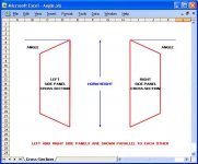
Then the “off-vertical” angle setting you need on your saw blade when cutting the tops and bottoms of the side panels is given by:
Angle = Arctan((X2 – X1) * (Y2 – Y1) / (4 * L12 * (L12 ^ 2 + 0.25 * (X2 – X1) ^ 2 ) ^ 0.5))
For example if:
X1 = 20
Y1 = 10
X2 = 40
Y2 = 30
L12 = 35
Then the required “off-vertical” angle = 4.49 degrees.
The attached sketch shows a not-to-scale cross-section view of the mouth-ends of the two side panels. For the purposes of indicating the required cutting angle, the two panels are shown parallel to each other in the drawing.
Hope this makes sense, and that it helps.
Kind regards,
David
Attachments
David McBean said:
Hope this makes sense, and that it helps.
Kind regards,
David
Wow David, I don't know what to say! Your post has certainly made my week. I've been chasing dead ends with this problem for a week now.
I don't know which is more impressive. The fact that you understood my question, or that fact that you knew how to solve it
.I just dusted of my old HP28S calculator and punched in the numbers from your example. Works like a charm!
Once again, thanks a million!
steve71 said:Once again, thanks a million!
Hi steve71,
No problems, glad to be able to help out
.Just to complete the picture, expressed in terms of angles (which was your original question), the formula becomes simply:
Angle = Arctan(Sin(AX) * Tan(AY))
Where AX is the half-angle between the left and right side panels of the horn, and AY is the half-angle between the top and bottom panels.
Kind regards,
David
steve71 said:I'm building a conical midbass horn loaded with an GPA 515G driver. It's based off of Erik's work at
http://www.volvotreter.de/pics/conical_horn_setup_06.jpg
FWIW, due to the driver's rising response I highly recommend you re-think your design to allow a 1:1 CR and lower Fhm same as all the Altec factory horn designs as well as optimizing for 2pi space, especially if yours has a vented DC.
BTW, are these measured specs as I notice they are somewhat different than those published?
GM
Re: Re: From Hornsrep to the drafting table.. How do I calculate this angle?
Thanks for the input GM.
I'll revisit the Keele equations (St & Fhm) and play around with horns rep's 2pi simulation and post up the results by tonight.
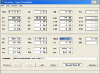
I'm not sure if the T/S parameters you're referring to are the ones in the link I provided (in this thread), but they are for the Electrovoice driver Erik used in his simulation. Here are the relevant T/S parameters I used (see attached pic). They were all taken off Altec/GPA's published specs. For Mmd (diaphragm mass) Hornsresp calculates 39 grams. I contacted Bill at GPA and asked him to measure the diaphragm mass of the 515G driver. He came back to me with 20.6- 25.2 grams (thanks Bill!!). IIRC anything under 40grams should allow an upper cut off (-3db) of 500hz according to HR, but I think the Keele equations suggests something around 250hz. Time to check my math.
I'm certainty no expert but I though the 515G was mated to the 288 compression driver which is used down to 500hz. Or was it just the 515B that was used in that configuration.
GM said:
FWIW, due to the driver's rising response I highly recommend you re-think your design to allow a 1:1 CR and lower Fhm same as all the Altec factory horn designs as well as optimizing for 2pi space, especially if yours has a vented DC.
BTW, are these measured specs as I notice they are somewhat different than those published?
GM
Thanks for the input GM.
I'll revisit the Keele equations (St & Fhm) and play around with horns rep's 2pi simulation and post up the results by tonight.
I'm not sure if the T/S parameters you're referring to are the ones in the link I provided (in this thread), but they are for the Electrovoice driver Erik used in his simulation. Here are the relevant T/S parameters I used (see attached pic). They were all taken off Altec/GPA's published specs. For Mmd (diaphragm mass) Hornsresp calculates 39 grams. I contacted Bill at GPA and asked him to measure the diaphragm mass of the 515G driver. He came back to me with 20.6- 25.2 grams (thanks Bill!!). IIRC anything under 40grams should allow an upper cut off (-3db) of 500hz according to HR, but I think the Keele equations suggests something around 250hz. Time to check my math.
I'm certainty no expert but I though the 515G was mated to the 288 compression driver which is used down to 500hz. Or was it just the 515B that was used in that configuration.
Attachments
You're welcome!
I was referring to the specs in your HR sim.
Hmm, so you're saying his published specs are pretty far off. Good to know.
Also, did he give you the Le = 0.58 mH spec?
FWIW, Vd/Xmax = Sd = 22.4"/0.17" = ~131.7647"^2 = ~850.09 cm^2.
Anyway, all point source horn drivers tend to have a response that looks something like this, so mating the horn to it is like matching up two drivers with an XO, i.e. the horn's HF response rolls off such that it blends with the driver's rising on axis response. Obviously, you can screw around with adding active or passive EQ to flatten its response, but acoustic solutions to acoustic problems is always best.
GM
GM said:You're welcome!
I was referring to the specs in your HR sim.
Hmm, so you're saying his published specs are pretty far off. Good to know.
Also, did he give you the Le = 0.58 mH spec?
FWIW, Vd/Xmax = Sd = 22.4"/0.17" = ~131.7647"^2 = ~850.09 cm^2.
GM
I couldn't find a published spec for Mmd from GPA or from the old Altec pdf's, but HR can calculate it from cms, sd & fs. Thielesmall.com has a value of 58.42 grams for moving mass (which includes the voice coil I guess), but nothing for Mmd.
I got the Le = 0.58mH spec from the old Altec pdf. "Voice coil inductance = 0.58mH"
That same spec sheet shows a Sd of 848.4cm^2 which is basically the same as you've calculated.
I've worked through all the Keele equations and used them as a starting point for my 2pi HR simulations. I think the FR looks usable (good even), but I'd love a second opinion from someone more knowledgeable than myself. I'll post a link to the thread when I post it up tonight.
Once again thanks for the help GM!
[edit]
I just realized that Mmd is supposed to include the voice coil weight, so I put Bill to all that trouble for nothing

At least that explains why HR calculates a value of 39grams. Oh well better to find my mistake now rather than after I've built the horn.
Here's the link to the new thread I've started discussing some of GM's suggestions (ie larger throat area & lower fhm).
http://www.diyaudio.com/forums/showthread.php?s=&postid=1587293#post1587293
If you get the chance, let me know what you think GM. It seemed to me that the larger throat rolled off the FR sooner (lower fhm) as you said, but playing with a smaller throat and smaller back chamber (ignoring Keeles Vb calculation for reactance annulling) seemed to yield a wider bandwidth. However as I keep saying, I have no practical experience with all this and I could be overlooking something simple.
steve71 said:
I got the Le = 0.58mH spec from the old Altec pdf. "Voice coil inductance = 0.58mH"
That same spec sheet shows a Sd of 848.4cm^2 which is basically the same as you've calculated.
I've worked through all the Keele equations........
Once again thanks for the help GM!
[edit]
I just realized that Mmd is supposed to include the voice coil weight.........
You're welcome!
Yeah, I wasn't thinking, the vast majority of 515s I've measured were 16 ohm models with 1-1.4 mH, so 0.58 mH falls right in the middle if 8 ohms.
Not sure what .pdf you're referring to for Sd, but it's wrong based on other known data, though in the scheme of things it's close enough for our purposes since you're not using actual measured specs. Not too surprising though as we've found numerous errors in Altec's published data when sharing known data on the Altec forum.
Never heard of Keele before I got on-line and since I use Prof. Leach's proven math I haven't bothered to delve into it.
Yeah, I meant to ask what exactly the 26 g was for since no 15" diaphragm/VC assembly I'm aware of weighs < 1 oz, but was apparently paying more attention to the Olympics than what I was typing.
GM
- Status
- This old topic is closed. If you want to reopen this topic, contact a moderator using the "Report Post" button.
- Home
- Loudspeakers
- Multi-Way
- From Hornsrep to the drafting table.. How do I calculate this angle?