hi all, long time reader and occasional contributor.
Of the many types of thread here, some of the most enjoyable are the construction threads, hopefully with lot's of pictures.
So with that intro, hopefully this will be an enjoyable thread to those of a similar mindset.
I was simply going to take pics along the way and then do a summary at the end, mainly because I can see this being quite a long build for one reason or another. But have had a change of heart, by chronicling it as I go it will help maintain the enthusiasm and keep me going. And I will be able to tap into the collective brains here if I hit problems.
First off, can someone point me to a 'how to' so I can include the photos in the thread? I think I've loaded a picture or two in my time, but it is usually the small picture at the bottom of the post that gets clicked on and pops up in a new window. There are evidently more savvy people here than me, and they manage to include the full size phot within the body of the thread, and whats more there are often more than one photo in the post itself.
I dunno how to do that, so help would be very much appreciated. Until I know how to do that I'll keep snapping the pics and insert them once I know how.
The speakers. I run 18 inch PHL bass units with a 6.5 PHL mid and a cabbasse tweeter. They are controlled with the deqx unit, so are tri-amped. When I get time, and if it's of interest, I'll post model numbers later.
They are currently in a rough set of boxes that have been the 'cut and shut' champs! Have had/tried a few different combos of drivers, the real constant is the 18s. So the current boxes bear the scars of bogging up and changing the position of the drivers etc. Want to change the angle of the box? no probs, nail a few bits of pine to the box and voila! So you can get a mental picture of what they might look like.
They were jokingly referred to once as the 'frankenspeaker', and like a lot of things the tag has stuck and they have ever since been affectionately referred to as the franks.
I hope that they end up as cindarella, or the beautiful swan after the ugly duckling.
The biggest problem in making a nice box??
Just HOW in the hell do you incorporate an 18 inch driver in the box and have it look nice??? The reams of paper that has been sacrificed in that pursuit!! Anyway, one fine day of doodling and I finally had something that looked halfway decent. Is it the best? doubt it, but hey I took it heh heh.
I have made a start, and so far it's actually looking great, even if I say so myself.
I would love to share it with you all, I hope you get some pleasure from it and indeed there may be a few things that some may get from it that will help them at some later stage.
And to be able to share it properly, I need to learn how to embed the pics within the post.
Thanks for looking, and shall wait for some cleverer minds than mine to explain the above trick.
see ya.

To post pics...
1. register onto a free picture hosting site, like
http://photobucket.com/
(there are many others, of course)
2. upload your pics there
3. copy the link address of the particular pic you need and paste in the post in between "" syntax.
Here is an example:
1. register onto a free picture hosting site, like
http://photobucket.com/
(there are many others, of course)
2. upload your pics there
3. copy the link address of the particular pic you need and paste in the post in between "" syntax.
Here is an example:
thanks for trying Aengus, you must be in the same boat as me.
Anyway, we may have a winner!! Cheers CLS.
OK, in appreciation of your efforts, we will now try your little theory, and see if it works.

And when I said frankenstein, you thought I was talking about my speakers didn't you!! heh heh maybe now you're sorry for helping??
One last thing to try, I now unveil to a wider audience
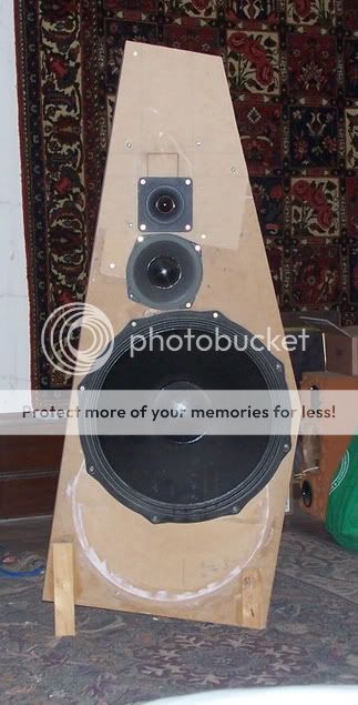
drum rollllll tah dah!~ the frankenspeakers
well, that went reasonably well for a first go, I couldn't seem to crop/edit them in photobucket, might try and edit them on the computer before I upload them. anyway, we seem to be off and running, thanks ever so much for your help.
Funny really, I have grown so used to them that I am almost fond of the looks, kinda cute really. I know, I know, a look only a mother could love. Heard it all before y'know?
They even say it about my speakers!
From memory, the 18s are the 8030s, the mids 1660 and the tweeter is the dom 40. the memory is a bit vague as I've had them for a few years now. I used to run a apair of 4 inch focals in d'appolito with the cabbasse, till I blew them up one day.
The replacement mid had to be of reasonable power handling I decided, and went for the 1660. As you can see, the box shows scars of many iterations, indeed the 'panel' holding the cabbasse I can see used to be the one that I tried the RAALs in, just make out the square shape. Just underneath you can see where I filled in the section trhat held the original focals. That also explains the tilt on the speakers (provided by only the best sounding 1*2 pine legs)..the focals and cabbasse originally were vertical, and when I put the PHLs in I just put them on a centre line with the bass unit, but had to then tilt the box to put the mid and tweeter vertical.
It will be kinda sad to see these boxes retired, but like a phoenix from the ashes a true beauty will emerge.
one last tip if you will, how do I resize the pictures so that they fit nicely on the screen (well, maybe only my screen) so that I don't need to use the scroll bar at the bottom?
I hope the thread will be as interesting to some as it is to me to build them.
cheers
Anyway, we may have a winner!! Cheers CLS.
OK, in appreciation of your efforts, we will now try your little theory, and see if it works.
And when I said frankenstein, you thought I was talking about my speakers didn't you!! heh heh maybe now you're sorry for helping??
One last thing to try, I now unveil to a wider audience
drum rollllll tah dah!~ the frankenspeakers
well, that went reasonably well for a first go, I couldn't seem to crop/edit them in photobucket, might try and edit them on the computer before I upload them. anyway, we seem to be off and running, thanks ever so much for your help.
Funny really, I have grown so used to them that I am almost fond of the looks, kinda cute really. I know, I know, a look only a mother could love. Heard it all before y'know?
They even say it about my speakers!
From memory, the 18s are the 8030s, the mids 1660 and the tweeter is the dom 40. the memory is a bit vague as I've had them for a few years now. I used to run a apair of 4 inch focals in d'appolito with the cabbasse, till I blew them up one day.
The replacement mid had to be of reasonable power handling I decided, and went for the 1660. As you can see, the box shows scars of many iterations, indeed the 'panel' holding the cabbasse I can see used to be the one that I tried the RAALs in, just make out the square shape. Just underneath you can see where I filled in the section trhat held the original focals. That also explains the tilt on the speakers (provided by only the best sounding 1*2 pine legs)..the focals and cabbasse originally were vertical, and when I put the PHLs in I just put them on a centre line with the bass unit, but had to then tilt the box to put the mid and tweeter vertical.
It will be kinda sad to see these boxes retired, but like a phoenix from the ashes a true beauty will emerge.
one last tip if you will, how do I resize the pictures so that they fit nicely on the screen (well, maybe only my screen) so that I don't need to use the scroll bar at the bottom?
I hope the thread will be as interesting to some as it is to me to build them.
cheers
I think I worked out the 'sizing' issue, we'll see.
I notice one of my pictures changed size, but not the other.
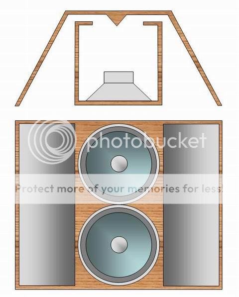
OK, the big prob was making a hulking big driver in a box look half way decent.
After much mucking about, the elevation looked like this.
Alright alright, best I could do m'k?
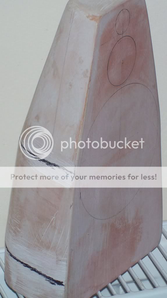
Went ahead and made a little model of it to get an idea if I was on the right track
I don't want to bore too many people with details, but there were a lot of lost hours trying to work out how to build the bloody thing. I mean it's all well and good having a 'fancy' design if it can't be built.
I have had the franks for a while now, and they have had a few drivers in them for evaluation, so as a result they have stayed 'ugly' all that time. It never bothered me in the slightest, indeed they have their own 'beauty' heh heh, but I can imagine that some may have thought that looks don't matter at all. Not really, but if I was going to the trouble of making nice ones then you can rest assured that they would be nice!
The easiest way I could imagine to build these was in laminated form, stacked layers of MDF.
My first tendency was to somehow laminate strips of nice wood (was thinking american walnut) around each layer, and once they were all stacked then somehow 'smooth off the steps', as each ascending layer would have been offset from the lower-as the front profile changes. (Was even contemplating getting reaaal fancy and iinserting a very thin brass shim between each layer of wood). That would have entailed building a steam unit to bend the strip of wood to follow the mdf layer, and meant that the rear corners needed to be rounded sufficiently enough to bend the steamed wood around the radius.
The rounded back radius on the model reflects that thinking.
Another alternative would be to veneer the box. That of course has it's own set of problems, one of which being that if I had the grain running vertically at the back, as it folded around the curve the grain would tilt. OK, so I could have cut the veneer in strips running vertically, wedge like if you will. I was reasonably sure I could have done that well enough, bit of a pain but do-able.
I went off the veneer idea because the biggest problem I foresaw was the horizontal joint between the veneers at each change of the front profile represented by the black lines you can see on the model.
I could see how I could easily make the basic shape ( I will give the formula later, by way of a simple geometric layout) and indeed had worked out a simple 'foolproof' jig method on manufacture, but was always getting stuck on the finish.
Dunno how it happened, but one day I had the brainwave of building the boxes in 'parts', sections. From the front profile you can see that it is three sections, each sitting on top of the other. The finished box will be one piece, but by doing it in sections I realised it allowed me to veneer it after all. The horizontal joint problem would be solved by smoothing the veneer to each section horizontally, and then stacking the sections together. No more the need to get that horizontal joint perfect on the completed box, it could be done as we went.
This will become clearer when I post more photos, but now that I was veneering it (no longer adding strips of wood to the mdf layers) I then did not need to have the rounded back corners, I could finish to a sharp corner. That is much more pleasing aesthetically, and was always my preferred option.
As I say, it will become clearer when the photos get uploaded.
I have learnt a few tricks that I really hope will be of use to others, look forward to sharing that with you all.
I notice one of my pictures changed size, but not the other.
OK, the big prob was making a hulking big driver in a box look half way decent.
After much mucking about, the elevation looked like this.
Alright alright, best I could do m'k?
Went ahead and made a little model of it to get an idea if I was on the right track
I don't want to bore too many people with details, but there were a lot of lost hours trying to work out how to build the bloody thing. I mean it's all well and good having a 'fancy' design if it can't be built.
I have had the franks for a while now, and they have had a few drivers in them for evaluation, so as a result they have stayed 'ugly' all that time. It never bothered me in the slightest, indeed they have their own 'beauty' heh heh, but I can imagine that some may have thought that looks don't matter at all. Not really, but if I was going to the trouble of making nice ones then you can rest assured that they would be nice!
The easiest way I could imagine to build these was in laminated form, stacked layers of MDF.
My first tendency was to somehow laminate strips of nice wood (was thinking american walnut) around each layer, and once they were all stacked then somehow 'smooth off the steps', as each ascending layer would have been offset from the lower-as the front profile changes. (Was even contemplating getting reaaal fancy and iinserting a very thin brass shim between each layer of wood). That would have entailed building a steam unit to bend the strip of wood to follow the mdf layer, and meant that the rear corners needed to be rounded sufficiently enough to bend the steamed wood around the radius.
The rounded back radius on the model reflects that thinking.
Another alternative would be to veneer the box. That of course has it's own set of problems, one of which being that if I had the grain running vertically at the back, as it folded around the curve the grain would tilt. OK, so I could have cut the veneer in strips running vertically, wedge like if you will. I was reasonably sure I could have done that well enough, bit of a pain but do-able.
I went off the veneer idea because the biggest problem I foresaw was the horizontal joint between the veneers at each change of the front profile represented by the black lines you can see on the model.
I could see how I could easily make the basic shape ( I will give the formula later, by way of a simple geometric layout) and indeed had worked out a simple 'foolproof' jig method on manufacture, but was always getting stuck on the finish.
Dunno how it happened, but one day I had the brainwave of building the boxes in 'parts', sections. From the front profile you can see that it is three sections, each sitting on top of the other. The finished box will be one piece, but by doing it in sections I realised it allowed me to veneer it after all. The horizontal joint problem would be solved by smoothing the veneer to each section horizontally, and then stacking the sections together. No more the need to get that horizontal joint perfect on the completed box, it could be done as we went.
This will become clearer when I post more photos, but now that I was veneering it (no longer adding strips of wood to the mdf layers) I then did not need to have the rounded back corners, I could finish to a sharp corner. That is much more pleasing aesthetically, and was always my preferred option.
As I say, it will become clearer when the photos get uploaded.
I have learnt a few tricks that I really hope will be of use to others, look forward to sharing that with you all.
Looks like a worthwhile endeavour!
I must say that I kind of like the runt enclosure being use now...
Makes me think of this...
Had you thought of having a non wood finish?
If you were building a stepped cross section translam out of MDF you could possibly use filler to smooth the steps together then give it a nice finish?
I must say that I kind of like the runt enclosure being use now...
Makes me think of this...
An externally hosted image should be here but it was not working when we last tested it.
Had you thought of having a non wood finish?
If you were building a stepped cross section translam out of MDF you could possibly use filler to smooth the steps together then give it a nice finish?
Terry, do you need the volume of the entire box for the 18" driver? I'm guessing not if you are splitting it into separate sections.
If that is the case, then why not go open baffle with the mid (if the PHL is suitable for that kind of enclosure), you would only have to build a nice front baffle then, and would make finishing it off a lot easier.
If that is the case, then why not go open baffle with the mid (if the PHL is suitable for that kind of enclosure), you would only have to build a nice front baffle then, and would make finishing it off a lot easier.

damn, made me go and check. yep correct brett, 7030. I like the blurb 'sound quality optimised over sensitivity'...then see it's 97 db efficient heh heh.
wondered what was going on doogy, see that the picture didn't load. You're correct (as you will see from the photos), it is perfectly feasible to have a non wood finish. I did indeed fill in with bog the steps that result from the diminishing layers. Do a good enough job of that and you would be set. However, a nice veneer (hopefully can source some antique australian cedar) fits in very nicely with the house itself. You may have noticed the skirting boards etc in my listening room, they are about 16 inches high and cedar. So to match would be wonderful.
Rob, yes the entire cabinet is sealed for the bass driver. The model I made above did not provide enough volume, so I had to deepen the box to get it. So the actual shape tho similar has turned out to be different. Need around 110 l.
I did try my drivers OB, but I'm afraid are not suitable at all. So sealed it is.
Oh man, hopefully this will get quicker!!
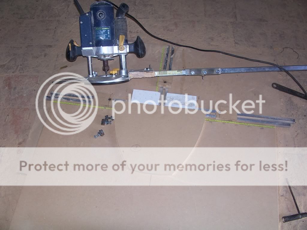
OK, the elevation I posted earlier was quite dirty, so I redrew it along with the associated plan and it's construction.

So we can see that it is all based on the fundamental dimension 'x'. As we rise up the front profile 'x' is constantly changing, and is of course based on the dimension of the layer in question. I look at the construction diagram should explain it a lot more easily than words.
Not sure if it will be clear in the picture, but the radius of the cut is always 1.2 x, this is the radius of the arm that the router rotates on.
The dpeth of the box is now 0.8 x, the model we saw earlier was 0.6x, but as I say did not give enough volume. A lucky side effect of the change is (I think) a nicer plan view. The model also reflected my first thinking of wrapping a strip of wood, hence had the pronounced radius which is no longer there, again leading to a nicer shape.
Next comes the jig. It needed to be foolproof..after all I was using it. It's a simple matter to have a small table based on 'x', listing out 1.2 x, .7x and .4 x.
As you can see from the construction diagram, by referencing from the origin, the pivot points then become 0.7 x. If I try to explain why it will be confusing, the diagram should make it clear why.
The 0.4x is of course because the depth of the box is 0.8 x (1.2x-0.8x = 0.4x). If I had stuck with a depth of 0.6x then the pivot would have been at 0.6x from the origin. Again it will be a lot clearer by looking at the diagram.
The arm the router is mounted on has a tape measure (invisible) that allows me to set the swing at 1.2x. The little wooden pieces have a pivot hole in them that the router mounts into, and they are set at 0.7 left and right, and 0.4 depth. All is adjustable. I simply bought some aluminium 'c' channel from the hardware store and mounted them as you can see. A small bolt pulls a plate up and locks the movable pivot points very securely indeed.
You can see a lamination set on the jig. It should be clear how it is done, all basically a 'compass' swing exactly as the original plan was constructed but using a router instead of a lead pencil. The only variable is x, all else follows.
this better get quicker, it's taken me an hour so far!!
I had the idea that it was going to take an awful lot of MDF to do this! So I decided to only cut the template for every fourth lamination, and 'fill in' with small blocks of mdf.
A shot of the test, with three blocks of mdf between each cutout.
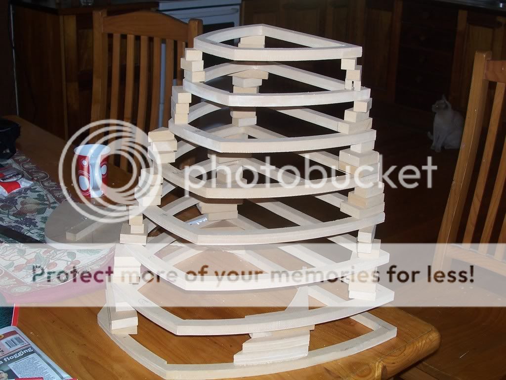
OK, time to go ahead. I used hide glue to stick the blocks in..it grabs fast and allowed me to very quickly add a block (bridging the two underneath), much more quickly than I could if I had used pva.
So the basic shape is starting to appear.
Well, that's enough for an hour and a half grrr..at this rate I may just stop!
Assuming it gets quicker for me I may add a bit more later.
gotta go and cool off.
edit. sorry, have to get the sizing right.
wondered what was going on doogy, see that the picture didn't load. You're correct (as you will see from the photos), it is perfectly feasible to have a non wood finish. I did indeed fill in with bog the steps that result from the diminishing layers. Do a good enough job of that and you would be set. However, a nice veneer (hopefully can source some antique australian cedar) fits in very nicely with the house itself. You may have noticed the skirting boards etc in my listening room, they are about 16 inches high and cedar. So to match would be wonderful.
Rob, yes the entire cabinet is sealed for the bass driver. The model I made above did not provide enough volume, so I had to deepen the box to get it. So the actual shape tho similar has turned out to be different. Need around 110 l.
I did try my drivers OB, but I'm afraid are not suitable at all. So sealed it is.
Oh man, hopefully this will get quicker!!
OK, the elevation I posted earlier was quite dirty, so I redrew it along with the associated plan and it's construction.
So we can see that it is all based on the fundamental dimension 'x'. As we rise up the front profile 'x' is constantly changing, and is of course based on the dimension of the layer in question. I look at the construction diagram should explain it a lot more easily than words.
Not sure if it will be clear in the picture, but the radius of the cut is always 1.2 x, this is the radius of the arm that the router rotates on.
The dpeth of the box is now 0.8 x, the model we saw earlier was 0.6x, but as I say did not give enough volume. A lucky side effect of the change is (I think) a nicer plan view. The model also reflected my first thinking of wrapping a strip of wood, hence had the pronounced radius which is no longer there, again leading to a nicer shape.
Next comes the jig. It needed to be foolproof..after all I was using it. It's a simple matter to have a small table based on 'x', listing out 1.2 x, .7x and .4 x.
As you can see from the construction diagram, by referencing from the origin, the pivot points then become 0.7 x. If I try to explain why it will be confusing, the diagram should make it clear why.
The 0.4x is of course because the depth of the box is 0.8 x (1.2x-0.8x = 0.4x). If I had stuck with a depth of 0.6x then the pivot would have been at 0.6x from the origin. Again it will be a lot clearer by looking at the diagram.
The arm the router is mounted on has a tape measure (invisible) that allows me to set the swing at 1.2x. The little wooden pieces have a pivot hole in them that the router mounts into, and they are set at 0.7 left and right, and 0.4 depth. All is adjustable. I simply bought some aluminium 'c' channel from the hardware store and mounted them as you can see. A small bolt pulls a plate up and locks the movable pivot points very securely indeed.
You can see a lamination set on the jig. It should be clear how it is done, all basically a 'compass' swing exactly as the original plan was constructed but using a router instead of a lead pencil. The only variable is x, all else follows.
this better get quicker, it's taken me an hour so far!!
I had the idea that it was going to take an awful lot of MDF to do this! So I decided to only cut the template for every fourth lamination, and 'fill in' with small blocks of mdf.
A shot of the test, with three blocks of mdf between each cutout.
OK, time to go ahead. I used hide glue to stick the blocks in..it grabs fast and allowed me to very quickly add a block (bridging the two underneath), much more quickly than I could if I had used pva.
So the basic shape is starting to appear.
Well, that's enough for an hour and a half grrr..at this rate I may just stop!
Assuming it gets quicker for me I may add a bit more later.
gotta go and cool off.
edit. sorry, have to get the sizing right.
calmed down a bit now..
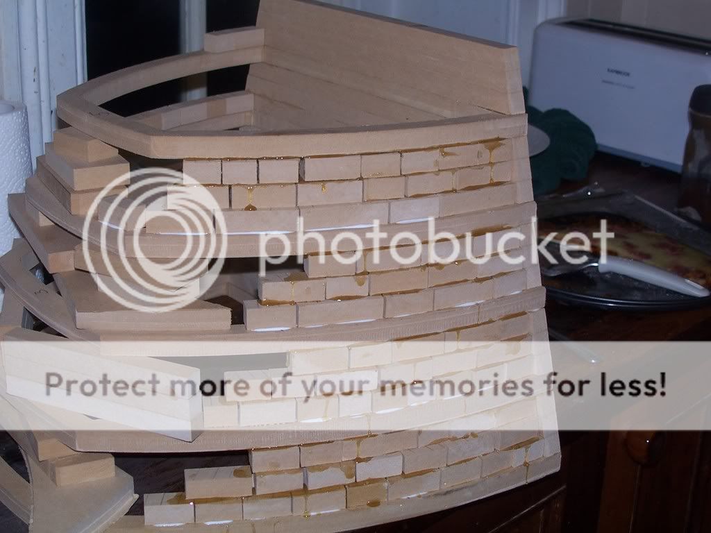
after the build of course comes the fill, use bog to fill the steps and provide a base for the three layers of 3mm mdf to go on top.
here are a couple of shots of the finished bog stage. As I had only cut every fourth layer, and filled in the rest, I could use the layers I had built as a witness to sand back the bog to. You should be able to make out the mdf just peeking thru the bog every fourth layer.

and a shot of the interior. I would like to spin you guys some yarn about deliberately having a rough interior, 'computer designed to optimise the break up of standing waves and provide internal diffraction of the sound waves' blah blah blah.
nope, just a by product of my construction technique.
It should be a bit clearer now, as they say a picture speaks a thousand words.
The part you see is the 'top' section of the model or plan elevation. It will be solidly joined to the 'middle' section. I will be doing a dry fit first to ensure alignment, but each piece will be veneered first. Now that the veneer comes to sharp edges, and has a definite 'bottom' to sand to, when I join them I have overcome the problem of a sharp horizontal veneer join I spoke of earlier.
The blocks and laminations are 16 mm deep, then filled in with bog and smoothed, then the three layers of mdf. should have a cross section of 30mm or so, yet gain extra strength from the curved shape.
so the mdf layers come next. As you may imagine, even tho the curve was not too severe, getting it to follow the shape whilst the glue was drying was a bit of a problem.
The first two layers I achieved it by many many small nails. Was a bit of a struggle simultaneously bending the mdf whilst nailing. Additionally, due I guess to differences in glue depth and clamp pressure whilst the glue was going off, the mdf side which should have been a 'flat' edge gained some depressions, as seen by the photo of a gap under a straight edge placed against the side.

(ahh, see that to get the picture in without scrolling along the bottom I need to upload to 640 by 480, will remember in future)
so some remedial action was required prior to the last layer of mdf going on. decided against bog, it has a very small working/plastic stage, then sets rock hard. Instead I used base coat usually used for setting gyprock (sheetrock?? or hardwall?? in the us?). Once it goes off it is also very hard, but to my delight I found it had quite a long working or plastic stage, when with a straight edge I could shave it smooth. I was happy enough with the results that I think I will use it instead of bog for the next time I fill the 'steps' on the external build up.
So with a smooth and even shape ready for the last layer (that is important, as the joints on the back of the box need to have a straight line, no 'waviness' or uneveness allowed!!) I somehow needed to get the final layer,which will be veneered, on the box without nails that might show thru the veneer. I was also a bit sick of wrestling with the essentially inflexible mdf layer.
Which leads me to the 'great unveiling'. I tried a little experiment with bending the mdf, and to my very great delight it worked a treat. I have not seen it used elsewhere, so even tho there is very little new under the sun, it just might be the case that this is the first time you have seen this in action!!
I hope this is of use to some of you in your future builds, I can see applications in many different builds, and no doubt there will be ideas you will come up with that have not even entered my head!
what? is that the time?? Ok, have to go right now but I will post pics tomorrow...heh heh heh.
after the build of course comes the fill, use bog to fill the steps and provide a base for the three layers of 3mm mdf to go on top.
here are a couple of shots of the finished bog stage. As I had only cut every fourth layer, and filled in the rest, I could use the layers I had built as a witness to sand back the bog to. You should be able to make out the mdf just peeking thru the bog every fourth layer.
and a shot of the interior. I would like to spin you guys some yarn about deliberately having a rough interior, 'computer designed to optimise the break up of standing waves and provide internal diffraction of the sound waves' blah blah blah.
nope, just a by product of my construction technique.
It should be a bit clearer now, as they say a picture speaks a thousand words.
The part you see is the 'top' section of the model or plan elevation. It will be solidly joined to the 'middle' section. I will be doing a dry fit first to ensure alignment, but each piece will be veneered first. Now that the veneer comes to sharp edges, and has a definite 'bottom' to sand to, when I join them I have overcome the problem of a sharp horizontal veneer join I spoke of earlier.
The blocks and laminations are 16 mm deep, then filled in with bog and smoothed, then the three layers of mdf. should have a cross section of 30mm or so, yet gain extra strength from the curved shape.
so the mdf layers come next. As you may imagine, even tho the curve was not too severe, getting it to follow the shape whilst the glue was drying was a bit of a problem.
The first two layers I achieved it by many many small nails. Was a bit of a struggle simultaneously bending the mdf whilst nailing. Additionally, due I guess to differences in glue depth and clamp pressure whilst the glue was going off, the mdf side which should have been a 'flat' edge gained some depressions, as seen by the photo of a gap under a straight edge placed against the side.
(ahh, see that to get the picture in without scrolling along the bottom I need to upload to 640 by 480, will remember in future)
so some remedial action was required prior to the last layer of mdf going on. decided against bog, it has a very small working/plastic stage, then sets rock hard. Instead I used base coat usually used for setting gyprock (sheetrock?? or hardwall?? in the us?). Once it goes off it is also very hard, but to my delight I found it had quite a long working or plastic stage, when with a straight edge I could shave it smooth. I was happy enough with the results that I think I will use it instead of bog for the next time I fill the 'steps' on the external build up.
So with a smooth and even shape ready for the last layer (that is important, as the joints on the back of the box need to have a straight line, no 'waviness' or uneveness allowed!!) I somehow needed to get the final layer,which will be veneered, on the box without nails that might show thru the veneer. I was also a bit sick of wrestling with the essentially inflexible mdf layer.
Which leads me to the 'great unveiling'. I tried a little experiment with bending the mdf, and to my very great delight it worked a treat. I have not seen it used elsewhere, so even tho there is very little new under the sun, it just might be the case that this is the first time you have seen this in action!!
I hope this is of use to some of you in your future builds, I can see applications in many different builds, and no doubt there will be ideas you will come up with that have not even entered my head!
what? is that the time?? Ok, have to go right now but I will post pics tomorrow...heh heh heh.
thanks for the comments so far guys.
Rob, seems I misunderstood your question. The bass driver was not suited for OB as I said, and it was always one of my plans one day to try the mids in ob config.
I have heard the Orions, and whilst very good to me I felt the midrange to be a little ephemeral and very much lacking in bite and punch. My first reaction was to discount ob (for me, others may of course love that and would hate mine) but then I realised it could be down to different drivers rather than a blanket 'no' to ob mids for me. So it was always one of my 'things to do'.
In any case, I DID fall in love with the ob bass, hence my experiment with these.
But to be totally honest, I listen to mine and think 'why in the heck bother, there is nothing broken so why 'fix' it??' In any case, I doubt these particular mids would be the ones to try OB, I'd go for some PHLs that naturally go lower, these are not ones to go much below 200 hz in a sealed box, think they may struggle in ob.
OK. I have the bog filled shell, now to skin with a couple of layers of mdf (3mm). That was fine as far as it went, 'cept for the probs listed earlier. It is a very hard job to get the stuff to bend nicely, took heaps of nails and tons of effort. But not suitable for the layer just under the veneer.
I had tried to put a bit of a set on the mdf first, tied a rope around the sheet to bend it into an arc and left it over night. that worked a bit and I'm sure must have helped somewhat, but the bend was what ever it ended up and not consistent throughout the sheet...but surely better than nothing.
I needed a better way.
So this is it. The great unveiling. I'm actually quite proud of it (and it probably shows) but still, it worked so well why not take a win when you get it?? And fiurther to that, I personally have never seen this trick done anywhere on forums or in building boxes. It may be out there but I at least have not seen it done before.
The frankentrick.
I had read this somewhere, on this forum. It was linked to a patent by someone, but I thought I'd modify it and give it a go.
And it's so simple!!

Here is the first experiment I did, the one that convinced me I was on a winner and the one that showed how to skin the box from here on out.
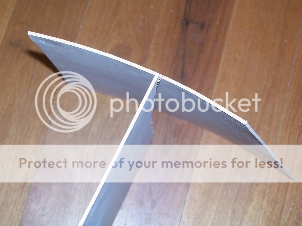
It is a test strip of 3mm mdf bent and clamped around a gas bottle..just grabbed whatever was handy for the experiment. about 3 inches diameter at a guess. as you can plainly see, it was no trouble at all. The clamps are only there till it dries.
The secret to the frankentrick? the next photo should explain it all. Next to the bent mdf is a similarly sized piece of mdf that was not fankentricked, and again you can clearly see that it was impossible to bend it around the gas bottle unlike the treated piece.
 \
\
I just used cloudy ammonia and 'painted' each side twice, not soaked or anything but as long as it took to paint (dampen with cloudy ammonia) it was then turned over and the same done again, then repeat. two coats on each side.
Straight away as simple as pie just bend it around the gas bottle, clamp it till the piece dries and bob is now officially your uncle.
The mdf goes an almost sickly green when painting with the ammonia, and returns to normal colour after the ammonia has evaporated from the mdf. It also regains all it's former strength.
So there it is, the first and no doubt the last contribution I personally will be able to make to the diy community collective knowledge. The frankentrick.
Happy as Larry with my success, it was onto the box. I simply cut a piece the same shape and size as I had been doing, painted each side in turn twice and then clamped it to the box and waited till it dried. the drying is of course affected by atmospheric conditions etc, also by things like the amount of clamps applied (that cover the piece and prevent easy access to the atmosphere), but anyway it does not take too long before it's all back to normal.
When I was applying the ammonia to the big board, you could almost feel it start to sag in your hands, and in only a minute or two.
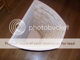
Here is a shot of the now preformed piece that 'exactly' follows the shape/contour of the thing it will be applied to (there is a very small bit of springback, maybe half a mm on each side in my example)
The picture may not show the extent, but the 'set' was considerable. It is leaning up against the same sized piece that would be used on the other face...one has been treated and the other yet to be treated.
How much did the frankentrick help on the last gluing step??
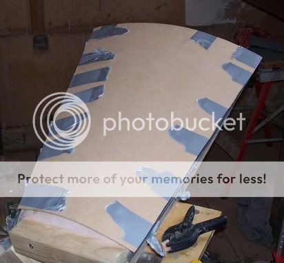
Instead of fighting the piece whilst glue has been applied to all surfaces and trying to bang heaps of little nails in, all I now need is a few pieces of tape. that obviously holds it in place and also takes the very slight springback (half a mm or so) out of the equation.
I think you would agree with me that it would be impossible to use a few strips of tape on an untreated board and be able to hold it down.
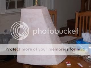
In a short while I'll quickly post the fully (three layered) finished top section.
Rob, seems I misunderstood your question. The bass driver was not suited for OB as I said, and it was always one of my plans one day to try the mids in ob config.
I have heard the Orions, and whilst very good to me I felt the midrange to be a little ephemeral and very much lacking in bite and punch. My first reaction was to discount ob (for me, others may of course love that and would hate mine) but then I realised it could be down to different drivers rather than a blanket 'no' to ob mids for me. So it was always one of my 'things to do'.
In any case, I DID fall in love with the ob bass, hence my experiment with these.
But to be totally honest, I listen to mine and think 'why in the heck bother, there is nothing broken so why 'fix' it??' In any case, I doubt these particular mids would be the ones to try OB, I'd go for some PHLs that naturally go lower, these are not ones to go much below 200 hz in a sealed box, think they may struggle in ob.
OK. I have the bog filled shell, now to skin with a couple of layers of mdf (3mm). That was fine as far as it went, 'cept for the probs listed earlier. It is a very hard job to get the stuff to bend nicely, took heaps of nails and tons of effort. But not suitable for the layer just under the veneer.
I had tried to put a bit of a set on the mdf first, tied a rope around the sheet to bend it into an arc and left it over night. that worked a bit and I'm sure must have helped somewhat, but the bend was what ever it ended up and not consistent throughout the sheet...but surely better than nothing.
I needed a better way.
So this is it. The great unveiling. I'm actually quite proud of it (and it probably shows) but still, it worked so well why not take a win when you get it?? And fiurther to that, I personally have never seen this trick done anywhere on forums or in building boxes. It may be out there but I at least have not seen it done before.
The frankentrick.
I had read this somewhere, on this forum. It was linked to a patent by someone, but I thought I'd modify it and give it a go.
And it's so simple!!
Here is the first experiment I did, the one that convinced me I was on a winner and the one that showed how to skin the box from here on out.
It is a test strip of 3mm mdf bent and clamped around a gas bottle..just grabbed whatever was handy for the experiment. about 3 inches diameter at a guess. as you can plainly see, it was no trouble at all. The clamps are only there till it dries.
The secret to the frankentrick? the next photo should explain it all. Next to the bent mdf is a similarly sized piece of mdf that was not fankentricked, and again you can clearly see that it was impossible to bend it around the gas bottle unlike the treated piece.
I just used cloudy ammonia and 'painted' each side twice, not soaked or anything but as long as it took to paint (dampen with cloudy ammonia) it was then turned over and the same done again, then repeat. two coats on each side.
Straight away as simple as pie just bend it around the gas bottle, clamp it till the piece dries and bob is now officially your uncle.
The mdf goes an almost sickly green when painting with the ammonia, and returns to normal colour after the ammonia has evaporated from the mdf. It also regains all it's former strength.
So there it is, the first and no doubt the last contribution I personally will be able to make to the diy community collective knowledge. The frankentrick.
Happy as Larry with my success, it was onto the box. I simply cut a piece the same shape and size as I had been doing, painted each side in turn twice and then clamped it to the box and waited till it dried. the drying is of course affected by atmospheric conditions etc, also by things like the amount of clamps applied (that cover the piece and prevent easy access to the atmosphere), but anyway it does not take too long before it's all back to normal.
When I was applying the ammonia to the big board, you could almost feel it start to sag in your hands, and in only a minute or two.
Here is a shot of the now preformed piece that 'exactly' follows the shape/contour of the thing it will be applied to (there is a very small bit of springback, maybe half a mm on each side in my example)
The picture may not show the extent, but the 'set' was considerable. It is leaning up against the same sized piece that would be used on the other face...one has been treated and the other yet to be treated.
How much did the frankentrick help on the last gluing step??
Instead of fighting the piece whilst glue has been applied to all surfaces and trying to bang heaps of little nails in, all I now need is a few pieces of tape. that obviously holds it in place and also takes the very slight springback (half a mm or so) out of the equation.
I think you would agree with me that it would be impossible to use a few strips of tape on an untreated board and be able to hold it down.
In a short while I'll quickly post the fully (three layered) finished top section.
- Status
- This old topic is closed. If you want to reopen this topic, contact a moderator using the "Report Post" button.
- Home
- Loudspeakers
- Multi-Way
- Frankenstein becomes cindarella..I hope!