Is there a document somewhere that explains how to do this? Is the final objective to flatten the on-axis response, or is there more to it than that? I tried searching, but 'eq' is too short for matches, and just the 'constant directivity' part turned up lots of discussions but nothing that seemed specifically targeted towards the EQ requirements.
I found the Peavey page that talks about this a bit:
http://www.peavey.com/support/technotes/soundsystems/horn_eq.cfm
And this post shows what a passive circuit might look like:
http://www.diyaudio.com/forums/showthread.php?postid=1378211#post1378211
And there are some posts talking about an R||C circuit, but I couldn't find anything that specifically described what this circuit should do, and how to calculate the component values. Is this a broad notch filter? A high-pass filter with the frequency set to the response peak? Something else? I can measure the driver/WG and mess with crossover components until it looks good, but some suggestions on where to start / how to proceed would be helpful 🙂
Thanks,
Saurav
Here's some info from Mackie.....
Here's a graph from TDM....
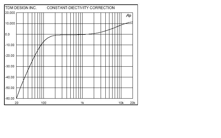
• Constant Directivity Horn EQ for smoother treble. To improve high frequency reproduction, many sound systems use constant directivity (CD horns). They improve treble dispersion by more evenly distributing high frequencies. But in doing so, they actually create a frequency "dip" that reduces important frequencies anywhere from 2.5kHz to 5kHz. The old way to compensate for this was a special crossover module (hard to find and usually expensive) or a graphic equalizer (nice try, but the "cure" is worse than the problem). The MÝ800, MÝ1400 and MÝ1400i include separate left and right CD horn EQ adjustments. This 6dB/octave EQ's "knee" position is sweepable from 2kHz to 6kHz — the high end boost is extended so you can add "Air" EQ even if you're not using CD horns.
Here's a graph from TDM....
There are different ways to approach it.
A simple R||C will do it, but the contour may not be optimal.
A parallel LCR notch gets it better.
The Altec 30923 "Bridged-T" filter does, too. I've posted an adjustable version of that, below, as was used in the Model 19 crossover, and others. "Input" is from your highpass filter, active or passive.
The Pi-Speaker crossover design tutorial lays it out. A long read, but worth it:
http://www.pispeakers.com/Speaker_Crossover.doc
Attachments

Saurav, a circuit that will provide appropriate constant-directivity equalization is described by Dickason in "The Loudspeaker Design Cookbook", in the chapter on crossover design. He calls it a "contour circuit".
The PiSpeakers tutorial linked to by Zilchlab is excellent, as it addresses this and other issues that will derail your crossover efforts if you don't address them.
Duke
The PiSpeakers tutorial linked to by Zilchlab is excellent, as it addresses this and other issues that will derail your crossover efforts if you don't address them.
Duke
Several points.
First the end response of a driver on a waveguide is far too complex to be correctly EQ'd with any cookbook approach. Every driver/waveguide combination is different. And what you need in the end is the correct acoustic response. Using any filter that does not take into consideration the actual system response will not work out very well.
It is terribly wrong to EQ'd to an axial response since there are many things that happen on axis which should actually be ignored. I EQ to the power response in the forward +-30° direction (just as JBL and many others do). I almost completely ignore the axial response since I don't recommend listening on axis.
My designs are closest to the Pi speakers approach, but are somewhat more complex. I use at least two parrallel LRCs and sometimes a series inductor to limit energy above 12 kHz (to protect the driver when the amp clips). No two systems of mine use the same topology, each one is optimized for the particular drivers.
Dr. Geddes,
Thank you for responding. I am well aware that this is a very complex undertaking to do right, but for now I'll be happy with something that's in the ballpark. So, to that end, I'm trying to understand what it is that this EQ needs to achieve. I will be measuring the driver/waveguide if I decide to try this.
I've downloaded the Pi Speakers document and will spend some time with it.
Thanks, that's the kind of information I was looking for.
Thank you for responding. I am well aware that this is a very complex undertaking to do right, but for now I'll be happy with something that's in the ballpark. So, to that end, I'm trying to understand what it is that this EQ needs to achieve. I will be measuring the driver/waveguide if I decide to try this.
I've downloaded the Pi Speakers document and will spend some time with it.
It is terribly wrong to EQ'd to an axial response since there are many things that happen on axis which should actually be ignored. I EQ to the power response in the forward +-30� direction (just as JBL and many others do). I almost completely ignore the axial response since I don't recommend listening on axis.
Thanks, that's the kind of information I was looking for.
The PI Speakers approach is about the least that one should do and if you can impliment that then you will be 90% there.
Try first to pad out the tweeter with a R ladder with one resistor across the driver and one in series. This is advantageous to reducing the driver impedance load. Then bypass the series R with a cap and adjust for HF level. I find that the LC combo for the high pass also plays a role in the RC function for the HF.
Finally you will have a peak in the response due to the drivers resonance and this can be tamed with the LRC across the driver. I generally find that there is a second peak above the driver resonance which is due to the resonance in the waveguide. Another LRC helps tame this one. In some cases there is another, a third one, and another LRC works. But by the time you have three LRCs in parrallel with the drivers impedance things get pretty hairy and difficult to tune. Generally the values become so precise that they are hard to obtain. In the ESP line we resorted to custom inductors because this was the only way to get the correct values.
Good luck.
Thank you once again. I have Speaker Workshop, so once I have the frequency and impedance measurements, I should be able to go through some iterations of trying different component values in software. And I can see that I need to measure the specific driver/WG combination I plan to use, or this won't work.
And as you said, I should do this with the goal of flattening out the +/- 30 degree power response, not the on-axis response. How many measurements do you take for this, and how do you weight/combine them? How close will I get by just using the 30 degree measurement and trying to flatten that?
And as you said, I should do this with the goal of flattening out the +/- 30 degree power response, not the on-axis response. How many measurements do you take for this, and how do you weight/combine them? How close will I get by just using the 30 degree measurement and trying to flatten that?
Saurav said:Thank you once again. I have Speaker Workshop, so once I have the frequency and impedance measurements, I should be able to go through some iterations of trying different component values in software. And I can see that I need to measure the specific driver/WG combination I plan to use, or this won't work.
And as you said, I should do this with the goal of flattening out the +/- 30 degree power response, not the on-axis response. How many measurements do you take for this, and how do you weight/combine them? How close will I get by just using the 30 degree measurement and trying to flatten that?
I do measurements every 7.5 degrees. I first work on flattening the 22.5 degree line and then check the whole polar response to see that I haven't made things terribly worse at other locations. I do tend to ignore the axial curve and put a lot of weight on the total power flatness. I think that you need good detail out to 90 degrees. I don't worry much about behind the source. I believe that I can hear a power response peak even if its response near the axis is not that great. The second resonance that I talked about tends to be a power response peak (a peak in the response at all polar lines) but is not so obvious in the near axial curves. In fact, on axis, its a hole, which is logical if its a resonance of the waveguide. You can imagine raising this level to correct the axial hole, thus pushing the power response way up - net result, a horrible sound.
- Status
- Not open for further replies.
- Home
- Loudspeakers
- Multi-Way
- Constant directivity EQ