Hi Svante
I tested with a different sound card today and different software to confirm frequncy and the results were the same.
I did however, remove the shelf brace that was near the port. This brace was solid and protruded greater than 50% across the enclosure. I think this is the wrong thing to do (I don't know because of my inexperience) as removing it has lifted the tuning from 66hz to 77hz. (that is with the port removed and just the 80 X 36 mm hole in the front baffle). So it looks like this was having some interaction with tuning.
I still don’t think it comes up to calculations though. After doing some more T/S measurements on my drivers and some more modeling I think a tuning of 65hz would be a bit better in my 14.5L enclosure. The port I am using has a plastic front plate and a cardboard tube. The I.D of the tube is 70mm but the hole in the plastic front plate is 65mm. So I don’t know which dia. to use in calculations. To get the 65hz tuning,I had to make the port 70mm long but using 65mm to do the calcs. I still get a required length if 95mm. I noticed that your calcs. in a previous post were shorter than mine and I would be interested to see what you get for this new configuration and if this is acceptable. I just don't know what an acceptable variance should be between calculations and actual measurements before thinking something is amiss.
Thanks
Thanks bjorno, I will have a look into this configeration.
Also, is it possible to use an alternate sampling frequency in the software? Sometimes soundcards gets confused about what sampling rate it is really using. This results in a shift in all measured frequencues. I have one at work that sometimes runs at 48000 Hz even though I tell it to run at 44100 Hz. If possible you could also try a completely different soundcard or computer.
I tested with a different sound card today and different software to confirm frequncy and the results were the same.
I did however, remove the shelf brace that was near the port. This brace was solid and protruded greater than 50% across the enclosure. I think this is the wrong thing to do (I don't know because of my inexperience) as removing it has lifted the tuning from 66hz to 77hz. (that is with the port removed and just the 80 X 36 mm hole in the front baffle). So it looks like this was having some interaction with tuning.
I still don’t think it comes up to calculations though. After doing some more T/S measurements on my drivers and some more modeling I think a tuning of 65hz would be a bit better in my 14.5L enclosure. The port I am using has a plastic front plate and a cardboard tube. The I.D of the tube is 70mm but the hole in the plastic front plate is 65mm. So I don’t know which dia. to use in calculations. To get the 65hz tuning,I had to make the port 70mm long but using 65mm to do the calcs. I still get a required length if 95mm. I noticed that your calcs. in a previous post were shorter than mine and I would be interested to see what you get for this new configuration and if this is acceptable. I just don't know what an acceptable variance should be between calculations and actual measurements before thinking something is amiss.
Thanks
As promised: Your drivers TS average used in a 14.5L aperiodic box tuned to 42 Hz (port length = 5.5” or 0.14 m, port dia = 1.38” or 70 mm): picture 1(3)-3(3).
Thanks bjorno, I will have a look into this configeration.
...The I.D of the tube is 70mm but the hole in the plastic front plate is 65mm. So I don’t know which dia. to use in calculations. To get the 65hz tuning,I had to make the port 70mm long but using 65mm to do the calcs. I still get a required length if 95mm...
Hi Brownee,
Using 65 mm diameter for port calculations and a length of 70 mm seems to be consistent for a 65 Hz tuning with your average TS data, i.e. IMO your measurements are ok but simulation attempts are of a lesser quality.
b
1(1)
Attachments
Brownee said:I did however, remove the shelf brace that was near the port. This brace was solid and protruded greater than 50% across the enclosure. I think this is the wrong thing to do (I don't know because of my inexperience) as removing it has lifted the tuning from 66hz to 77hz. (that is with the port removed and just the 80 X 36 mm hole in the front baffle). So it looks like this was having some interaction with tuning.
<snip>
I noticed that your calcs. in a previous post were shorter than mine and I would be interested to see what you get for this new configuration and if this is acceptable.
Ok, that is good that you found part of the explanation. Possibly it would be easier to go on if you had a photo of the box and also of your measurement of the impedance.
I did my calculations in Basta! in my signature, you can download it and try for yourself. The free version does this.
Hi bjorno
I appreciate your candidness and thanks for the help you are giving me. I am on a steep learning curve and still unsure of what I am aiming for with regard to simulation.
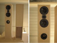
Could you tell me what aspects of the simulation is the problem and what I should be aiming for? I am doing lots of reading but there seems so many ways of doing things. I have built the cabinets as floor standers and there is room at the bottom to increase the volume without much trouble if need be. I just need to get this simulation sorted.
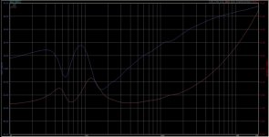
Hi Svante, here is the impedance sweep and some pictures of the enclosure.
Thanks
Brownee
IMO your measurements are ok but simulation attempts are of a lesser quality.
I appreciate your candidness and thanks for the help you are giving me. I am on a steep learning curve and still unsure of what I am aiming for with regard to simulation.
Could you tell me what aspects of the simulation is the problem and what I should be aiming for? I am doing lots of reading but there seems so many ways of doing things. I have built the cabinets as floor standers and there is room at the bottom to increase the volume without much trouble if need be. I just need to get this simulation sorted.
Possibly it would be easier to go on if you had a photo of the box and also of your measurement of the impedance.
Hi Svante, here is the impedance sweep and some pictures of the enclosure.
Thanks
Brownee
Attachments
Its very interesting that removing the brace altered the tuning.
I think its easy to get hung up on hitting an alignment exactly. You have to remember that temperature, manufacturing tolerances, drive level etc all move the TS parameters away from the datasheet values.
I forgot to say, an easy way of checking if the port is coupling with the enclosure properly is to listen to it. It sounds obvious but is easily overlooked!
If you put your ear close to the port at a moderate level and the output is comparable in output to the main drivers in level and has the expected bass bias then you are on the right track! If it sounds good it is good.
Nice to see you are making progress.
Simon
- Status
- This old topic is closed. If you want to reopen this topic, contact a moderator using the "Report Post" button.
- Home
- Loudspeakers
- Multi-Way
- What’s going on with my port tuning?