
Don't get me wrong, I'd love to see a meaningful investigation how room reflections influence spatial reproduction. But I don't see anybody trying anything in a meaningful way. Basic requirements for listening tests are ignored. That's why I bought a Smyth Realiser to hopefully gain some insight how my own spatial perception is affected.
Would you advice the best arrangement for a such a test? I'll place the speaker on the floor facing upwards.
If drivers from the same brand and the same series just with different sizes work so differently and and a driver of an other brand again I am not sure if one can advice anything. And for a non-stereo-hearer maybe it is a different cup of tea again, even if listening mono. I agree with Oliver that one has to distinguish between concepts and implementations. I once told someone about the flooder in a german forum and it worked for him with the 8" Beyma in the "Viech". The "Viecher" were lying on the floor and he was sitting on the floor. The Beyma in a quasi-IB enclosure would be a cheap and simple try.
What interests me more: Can a "non-stereo-hearer" hear stereo with Sonabs?
Last edited:
...
it is absorption (togehter with directivity of the loudspeaker) that causes this fall of overall radiated power in function of frequency, isn't it?
...
Typically not. A pistonic acting dynamic speaker has a frequency range
where it's radiated power is more or less constant.
That range is above resonance and below the frequency where it becomes
directional. Falling VC velocity with frequency is in that range compensated
by increasing radiation resistance.
Above that frequency the radiated power falls off.
Radiation resistance does not increase anymore, falling VC velocity
is no more compensated, VC inductivity leads to driving force falling
with frequency.
A falling power output of 12db / Octave is the result above that
constant range.
A fullranger can keep ON AXIS pressure level constant above that
"constant power" range by beaming, which means radiating
the power into a narrower angle. Nevertheless, the total
power falls off.
The dynamic speaker itself is the reason for acoustic output power
falling with frequency above the non-directional frequency range.
The transitions between the frequency ranges are design dependent.
Non pistonic behaviour of the cone, VC inductivity etc. influence
the behaviour of a given driver, but physics governs the overall
pattern, giving an individual driver only small space for variation.
Best
Last edited:
Hello Graaf,
- Elias
Hello,
actually el`Ol has already answered to Your questions
I would only like to add that I have never flooded such conventional two-way speaker, only fullrange 8 '' Fostex, various cheap fullrangers and two-way coincident UniQ KEFs
I had intuition that conventional multi-way would be unsuitable but I could be wrong of course.
It is terra incognita.
As regards placement - it all depends, if the loudspeaker is bass-reflex it can react unfavourably to near wall or near corner placement and so on
anyway I would start with near wall placement with the wall in the vicinity of the speakers left reflective without any absorption and listening position at least 3 m away from the speaker
what do You mean by side wall? In mono setup there is no side wall
")
happy experimenting!
graaf
Last edited:
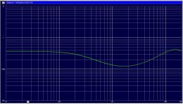
The curves are the voltage transfer functions for the
lower and the upper trio of drivers in Dipol 08.
The rising voltage in the brilliance region is a least
partially motivated by compensation of output power
decrease.
Additionally the power is shifted towards the upper
trio, to make the array shorter effectively at high
frequencies.
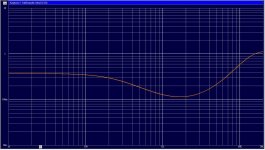
lower and the upper trio of drivers in Dipol 08.
The rising voltage in the brilliance region is a least
partially motivated by compensation of output power
decrease.
Additionally the power is shifted towards the upper
trio, to make the array shorter effectively at high
frequencies.
Attachments
That's why I bought a Smyth Realiser to hopefully gain some insight how my own spatial perception is affected.
Strange product. Good for our discussion, but does it really made sense to simulate loudspeakers in a virtual room for getting ideal headphone playback? For example: Isn't it an advantage to have low crosstalk with headphones?
Nice explanation, Oliver, but some fullrangers have tons of copper around the polepiece.
That may reduce the VC inductivity but cannot compensate
the major effect of VC velocity falling with frequency due to
mass inhibition of the vibrational system.
VC inductivity just adds another 6db /Octave. You cannot
make inducivity zero, you can of course shift the full
12db/Octave power slope towards higher frequencies.
You can just shape the transition regions as said before.
Make a whizzer or a dustcap decoupling from the main cone,
(loosing mass with increasing frequency, yeah ...!)
keep VC inductivity low ... all the tricks used to make a
fullrange instead of "dullrange".
Physics governs. Btw. a whizzer cone e.g. and less stiff glue
for the main cone while attaching the whizzer hard to the VC is
de facto a mechanical 2-Way ... with all the consequences.
Often overlooked by fullrange purists.
But my reason for explaining was that high frequency power
cuttoff is typically due to the physics of the dynamic
fullrange driver itself and not due to the listening room.
To come back to the threads title ...
Strange product. Good for our discussion, but does it really made sense to simulate loudspeakers in a virtual room for getting ideal headphone playback?
If you take into account the hourly rate of a professional studio, absolutely!
But isn't it the tons of equipment that makes a studio expensive, not the specific monitors in a specific room?
Depends on how you mix. If you're mixing in the box, then the expensive part is the room itself.
To come back to the threads title ...
I had good highs with the HX201 and this guy had insufficient highs with the Beyma, but still the spacial effect he liked. Of course I can not be sure that he had the same effect as I had, but this made makes me believe that energy distribution is not so critical.
Depends on how you mix. If you're mixing in the box, then the expensive part is the room itself.
Then why not mix at home from the beginning instead of carrying the studio home?
@graaf concerning ceiling flooder and "mini wideranger array"
The "phase controled mini wideranger array" could be used to
investigate the ceiling flooder approach in a systematic manner.
Radiation pattern could be varied from simulating
a "small fullranger"
a "big fullranger" with radiation pattern narrowing at even lower frequency
a "constant directivity" pattern.
An adjustable delay for the woofer could be given listeners at
hand to adjust a preferable delay dependent from the setting.
If the listeners choose no delay, you know that it is not needed.
Just a thought experiment. Thought experiments are very cheap
unless done real.
Last edited:
I had good highs with the HX201 and this guy had insufficient highs with the Beyma, but still the spacial effect he liked. Of course I can not be sure that he had the same effect as I had, but this made makes me believe that energy distribution is not so critical.
You mean "not essential" for the "ceiling flooder spatial effect" ?
But if there is an effect different from an omni source it must
be due to radiaton pattern ... or has my logic left me somewhere
in the depth of this thread ?
Or do you mean spectral energy distribution is not essential ?
Last edited:
Of course the change of the polar response with changing frequency is important, but what does that have to do with your talk about voice coils and so on?
A fullranger firing towards the ceiling is not able anymore
to compensate falling VC velocity
- which is the reason for falling acoustic power with frequency-
by beaming at the listener to exhibit flat sound pressure response.
It is like measuring the sound pressure off axis. You get a strongly
falling pattern for a t y p i c a l driver.
This may rise the need for compensation, when a typical driver
is used for that purpose. That is all i want to say.
Last edited:
If you don't want to tell us your speaker placement, then at least the decoder?
If not, here is some reading stuff about an other strange system:
Andrea von Salis - The reproduction system
I posted the speaker placement earlier. I've been to that site before but never tried that one so I can't say much. Same basic concept except I don't have any euphonic knobs and mine probably works better
In that regard I agree with what Markus was saying earlier that these things should just work and not need a bunch of tinkering and knob turning. It's pretty easy for me to set up situations with a knob that can drastically stretch, warp, or smear the imaging the hard part is giving the user an "un-distort" button that just works.I posted the speaker placement earlier.
You mean this coloured picture with the "hexaphonic" thing?
And the decoder?
Just a thought experiment.
nice!
Thought experiments are very cheap
unless done real.
unfortunately
best,
- Home
- Loudspeakers
- Multi-Way
- The Advantages of Floor Coupled Up-Firing Speakers