Not a big deal - but you want your initial impulse to move positive - looks like your drivers are wired backwards.
Do not move the mic at all between impulse measurements and actual FR measurements. Otherwise you are not obtaining the true acoustic offset between drivers. If you leave the mic on the tweeter axis for the woofer measurement, then your woofer impulse will be slightly later, so your acoustic offset is greater.
If you are going to model your crossover in another package than SW (or use SW driver offset values in modeling the XO) - then what you did is fine. You'll need to export, HBT the data then reimport for SW. Don't forget to enter acoustic offset in the other package you might be modeling in.
otherwise (if using SW all the way through) ... leave the mic in one place, measure responses and use the actual measured phase when designing the crossover. Moving the mic between driver measurements will invalidate SW measured phase - making crossover simulation inaccurate.
David.
I just moved the mic up and down to align it with the respective driver at a distance of about 3 inches.
Do not move the mic at all between impulse measurements and actual FR measurements. Otherwise you are not obtaining the true acoustic offset between drivers. If you leave the mic on the tweeter axis for the woofer measurement, then your woofer impulse will be slightly later, so your acoustic offset is greater.
If you are going to model your crossover in another package than SW (or use SW driver offset values in modeling the XO) - then what you did is fine. You'll need to export, HBT the data then reimport for SW. Don't forget to enter acoustic offset in the other package you might be modeling in.
otherwise (if using SW all the way through) ... leave the mic in one place, measure responses and use the actual measured phase when designing the crossover. Moving the mic between driver measurements will invalidate SW measured phase - making crossover simulation inaccurate.
David.
Thanks for that excellent advice Dave. I guess for near field measurements in SW, I do have to move the mics. What about the on axis response? Do I keep the mic position (centered at the tweeter) the same for tweeter and mid range driver measurements?
Also I did have the drivers wired backwards.
So by using the mic in one place do I still need to input the acoustic offset? My tweeter is recessed by 1.4" so do I have to put -1.4" in the tweeter acoustic offset?
I'm still new at SW and learning so thanks for your insight.
Also I did have the drivers wired backwards.
So by using the mic in one place do I still need to input the acoustic offset? My tweeter is recessed by 1.4" so do I have to put -1.4" in the tweeter acoustic offset?
I'm still new at SW and learning so thanks for your insight.
Hi there,
if you are measuring nearfield with a view to splice into farfield to estimate things like required BSC or overall response - that's fine.
However - I would avoid using nearfield for xo simulation. For the 2 way you are talking about, you should be able to get a gated farfield measurement with a 5msec gate in most rooms. This would give you sufficient FR resolution for xo modeling.
Lowest measured frequency = 1000 / gate (in msec). Hence 5msec will give you measurements down to 200Hz. Fine for xo modeling.
You want at least 256 data points for enough resolution for xo simulation.
To work out the start marker for the impulse - measure the driver whose acoustic centre is closest to the mic. This is usually the tweeter. Reason to place the marker on the tweeter measurement first, is if you do the woofer and it is delayed, you will miss the tweeter impulse when you switch to measuring tweeter response. You can't move the marker between measurements as I previouslynoted... therefore start with tweeter measurements.
If you don't move markers or microphone - then all drivers in your crossover should have a zero offset. IT is only if you use externally generated data (not measured by SW itself) or you move the mic around between measurements that you need to enter an offset. For SW - negative values are "into" the enclosure / baffle (ie. further away from the mic). Positive values would protrude from the baffle (ie. closer to the mic).
Hope that helps.
Cheers,
DAvid.
How rude - I didn't even answer your question...
For the on-axis response you are correct. For measuring both woofers and the tweeter - leave the mic on axis to the tweeter throughout.
Jay has a section on how to measure and model doubled up woofers in an MTM config. I can't recall the specifics right now.
Cheers,
DAvid.
guess for near field measurements in SW, I do have to move the mics. What about the on axis response? Do I keep the mic position (centered at the tweeter) the same for tweeter and mid range driver measurements?
For the on-axis response you are correct. For measuring both woofers and the tweeter - leave the mic on axis to the tweeter throughout.
Jay has a section on how to measure and model doubled up woofers in an MTM config. I can't recall the specifics right now.
Cheers,
DAvid.
To work out the start marker for the impulse - measure the driver whose acoustic centre is closest to the mic. This is usually the tweeter. Reason to place the marker on the tweeter measurement first, is if you do the woofer and it is delayed, you will miss the tweeter impulse when you switch to measuring tweeter response.
Thanks once again DAvid. I don't understand what you mean by marker; is it the gate setting? In my case the tweeter is closest to the mic.
Also if you do recall the article/resource that you mentioned about Jay (measuring MTM conficuration) please do let me know.
Also, what you said about measuring the near field frequency response of the mid drivers from the same position as the tweeter makes so much sense. When I moved the mic previously I was getting a lot of comb filtering especially at 5k with a -30db notch. By keeping the mic position the same I probably eliminated this destructive interference between the two mid range drivers.
Thanks once again DAvid. I don't understand what you mean by marker; is it the gate setting? In my case the tweeter is closest to the mic.
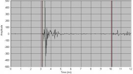
Yes - you've got it.. If you cannot see the start marker when viewing your impulse measurement, it may not be turned on. Go to the Options menu -> preferences then select the markers tab. You'll see three checkboxes. Check the time marker. This is used to set the start and end markers. The difference is your measurement gate. You can drag / drop the markers into position. If you want to be precise about placement - you can set in the options -> preferences as above. Sometimes it is hard to drag the marker off the zero position, so I use options -> preferences to set say to 1msec then drag from there. Here is an example of an appropriately placed start marker.
The way the markers are observed are as follows:
on-axis - between start and end marker
gated - start marker only - no end marker
farfield - no start or end markers. Usually used to measure response in room where you don't care about phase or reflections
For crossover measurements - you want the on-axis and related family of curves (30 and 60 in speakerworkshop - but you just angle your speaker to whatever you want to measure and rename the output data created).
The
Also if you do recall the article/resource that you mentioned about Jay (measuring MTM conficuration) please do let me know.
Jay's manual can be downloaded from Claudio's site here if you don't already have it:
http://www.clane.netsons.org/sw%20manual.zip
The section on MTMs is Page 185 (in the 6th MS word document).
Also, what you said about measuring the near field frequency response of the mid drivers from the same position as the tweeter makes so much sense. When I moved the mic previously I was getting a lot of comb filtering especially at 5k with a -30db notch. By keeping the mic position the same I probably eliminated this destructive interference between the two mid range drivers.
That's right. One of the benefits (or pitfalls) of the MTM is the symmetrical vertical polar response, hence you want the mic smack bang in the middle of the M's - usually tweeter axis. Of course you should be designing the height of the speaker so that you'll end up listening on the tweeter axis in this case. You can offset the tweeter horizontally on the baffle if it helps smooth diffraction ripple. Don't forget to pay attention to off-axis (horizontal) curves. Don't get too hung up about a perfectly flat on-axis response. This usually means your off-axis curves will suffer and that's where we often spend most of our time listening. You want a good power response.
Cheers,
David.
Below is a sample impulse response for a Seas 27TBFC/G. Note the start marker just before the impulse, and end marker before the first reflection:
You can advance the start marker even further before the impulse (it doesn't have to be just before the impulse). The benefit with advancing the start marker (ie. making closer to or at zero) - is it increases the gate length = greater resolution in SW.
The disadvantage is you will get more phase wrapping potentially making crossover design more difficult.
For most measurements - a sample rate of 48K and sample size of 65000 work well.
Cheers,
David.
Attachments
Thanks Dave, I havn't gotten to measurements as yet. I spent finishing the enclosures today. The veneer is a sapelle pomelle and looks really nice; the pictures don't do them justice. I finished it off by spraying a couple of medium gloss lacquer coats.
Attachments
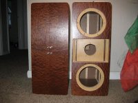
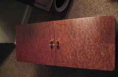
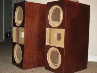
The cabinets look beautiful. The veneer is great.
The only concern is the way you have recessed the tweeter. The cavity might cause some nasty diffraction effects, requiring more crossover work to smooth out.
If you are recessing to time-align the drivers, that is not necessary. You can usually achieve this via some asymmetry in your crossover slopes
David.
Hey Dave, glad you like it. I'm really happy with it as this is really my first project. i'm basically cloning the Lipinski L 707 which in turn were inspired by the truly venerable Dunlavys.
http://www.lipinskisound.com/l707.aspx
Just like these, I'm using an open cell foam for the tweeter surrounds. Inductor has been helping me out with the crossover which is a non symmetric crossover. The tweeter is a second order LR while the mid range driver has a first order butterworth.
Once I have these hooked up I'll be able to take some good measurements with SW and fine tune the network from there.
I'll post some more pics soon... and thanks again
Jason.
Hi burnett,
Also have in consideration that this xover was designed with both woofers being identical, and not in a typical d'Appolito configuration, with them working one as a woofer and another as a midwoofer. There's a lot (of interesting things) that can be done/tested...
Also have in consideration that this xover was designed with both woofers being identical, and not in a typical d'Appolito configuration, with them working one as a woofer and another as a midwoofer. There's a lot (of interesting things) that can be done/tested...
Hi inductor,
thank's for chiming in again. I did realize that the crossover treats the woofer in parallel configuration.
Sadly those Vifa MG are nowhere to be found due to being discontinued quite some time ago.
In the meantime I came across this speaker: http://www.emes.de/pageseng/products/eblue/eblue.html
Specs are really great, and as far as I could investigate they use all scan speak drivers.
Hi burnett,
Are you building a new set of speakers? (we can ask the administrator to start a new tread for you, if you want later). What are you looking at, besides the MTM, drivers, etc, you want a good low end, like this is a mid woofer w/no woofer (sow to say) and it's ressonant frequency must go deep to the 30's(/20's). So you are looking at a 2in1 job, right.
Are you building a new set of speakers? (we can ask the administrator to start a new tread for you, if you want later). What are you looking at, besides the MTM, drivers, etc, you want a good low end, like this is a mid woofer w/no woofer (sow to say) and it's ressonant frequency must go deep to the 30's(/20's). So you are looking at a 2in1 job, right.
Hi burnett,
take the 17WN225 of Vifa, as I did in my before mentioned speakers. They are still the best 7" of Vifa. You won´t find better signal handling in any of the more modern designs. I´m pretty sure they perform minimum on the Lipinsky´s level. At least they measure better in many aspects. And they are absolutely easy to drive with a 20W tube amp beeing more than sufficient.
jauu
Calvin
Yes, and there are many kevlar cones in the market, also consider Davis,
Davis 17KLV 6A
This Vifa woofer, $45.21 EA (4+), has a Fs=37Hz, not so highish, from PE
Vifa P17WJ-00-08
The best thing would be to have 3 or 4 and simulate them with the front baffle.
...And for the tweeter, maybe a Mivoc KFT 130M (EUR 49,00), or other, that you can turn 0º and 90º, rotating it on the baffle, with a special square support behind. Or a Davis TW26 K tweeter with kevlar cone for that matter. Have fun.
Thank you Inductor & Calvin for all those hints and advices. I'll take all this input into consideration, spend some more time to evaluate my needs more precise and come back if I'm really ready to get things started.
I might have taken this a bit too easy")
But it's good to know that there are "wise" people out there.
I might have taken this a bit too easy
But it's good to know that there are "wise" people out there.
- Status
- This old topic is closed. If you want to reopen this topic, contact a moderator using the "Report Post" button.
- Home
- Loudspeakers
- Multi-Way
- MTM project using 7" vifa drivers