Hey everyone,
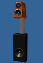
I have this unusual design situation for a high quality speaker for a computer desk near field monitor. The speaker needed to fit up tight to the desk and also into a wall corner on one side. The head unit needed to be rotatable in relation to the base to give flexibility in placement.
I came up with this design and I want to use the integrated stand pillar as a combination aperiodic vent and BR vent. This is my idea and I need to know what you guys think.
There are two sets of drilled holes in the round upper cabinet stand and a bulkhead that separates the two. Both ends of the pillar are open into the upper and lower cabinets. The upper cabinet is aperiodically loaded by stuffing the upper portion of the tube near the small holes with a filling material. Varying the density until the proper resistance is dialed in.
In order to maximize space inside the lower cabinet I thought that it would be cool to use the pillar as the vent but in order to do so I need to make a distributed port. The port consists of many small holes whose size is tuned to the proper resonance frequency by varying the thickness of the piller and diameter of the hole in the lower section. I figure that I need enough holes to approximate the area of one larger vent.
Any feedback? Here is concept render picture. I though this would be interesting solution for this situation and be able to give high end sound quality. I wanted to give the upper cabinet a kind of curved interesting look. The base has a small footprint and will be maybe 1.25 cubic foot enclosure for an 8-9 inch woofer.
Attachments
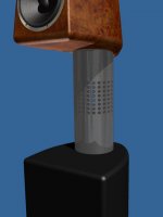
Here is a close up of the pillar and holes. My question is how close do I need to have the holes to the cabinet. Since I wonder if the internal volume of the pipe could also act as a resonant pipe. Or would the leakage of the holes be enough to cancel this.
Attachments
I'd could go sealed if necessary but I do not favor sealed loading unless I can get a critically damped alignment.
If the holes were moved down closer to the cabinet and if there were enough of them I don't think that woshing noise would be a problem. Since these will mostly be listened to at lower volume levels. But I think it would require quite a few holes.
If this doesn't work out I may go with aperiodic for the bass cabinet also. I guess what I need to do is built a test cabinet for the bass. Or maybe just test the final cabinet before assembly. Since I could have different configurations of tube without having to redo the cabinets. The tubes will slide in and out with a friction fit and since the head unit needs to rotate they will not be glued together.
This design seems to lend itself to testing by just changing the tube configuration.
Hi Hezz,
I suggest you try that idea.
Keep all holes at the rear of the mounting pipe so that you can make the front presentable looking, say with lengths of chrome pipe or cut lengths of colour co-ordinated or wooden venetian blind strips.
Many holes over a larger area might not generate noticeable turbulence, but the highest pressure/velocity is most likely to arise through those closest to the bass enclosure. The beauty of this design being that you can tape over the holes and then remove to optimise bass for the loudspeaker's individual room position.
The biggest problem however is the pattern looking irregular due to even the tiniest of errors accumulating within the matrix.
Another option is to drill more holes than necessary and try different cover clothes to both mask any hole irregularities and provide resistive damping.
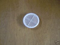
When I tried similar myself I ended up not using the drilled holes but simple DIY vents formed from 7cm dia builder's Soffit Vents.
Cheers ............ Graham.
I suggest you try that idea.
Keep all holes at the rear of the mounting pipe so that you can make the front presentable looking, say with lengths of chrome pipe or cut lengths of colour co-ordinated or wooden venetian blind strips.
Many holes over a larger area might not generate noticeable turbulence, but the highest pressure/velocity is most likely to arise through those closest to the bass enclosure. The beauty of this design being that you can tape over the holes and then remove to optimise bass for the loudspeaker's individual room position.
The biggest problem however is the pattern looking irregular due to even the tiniest of errors accumulating within the matrix.
Another option is to drill more holes than necessary and try different cover clothes to both mask any hole irregularities and provide resistive damping.
When I tried similar myself I ended up not using the drilled holes but simple DIY vents formed from 7cm dia builder's Soffit Vents.
Cheers ............ Graham.
Attachments
Graham Maynard said:Hi Hezz,
I suggest you try that idea.
Keep all holes at the rear of the mounting pipe so that you can make the front presentable looking, say with lengths of chrome pipe or cut lengths of colour co-ordinated or wooden venetian blind strips.
Many holes over a larger area might not generate noticeable turbulence, but the highest pressure/velocity is most likely to arise through those closest to the bass enclosure. The beauty of this design being that you can tape over the holes and then remove to optimise bass for the loudspeaker's individual room position.
The biggest problem however is the pattern looking irregular due to even the tiniest of errors accumulating within the matrix.
Another option is to drill more holes than necessary and try different cover clothes to both mask any hole irregularities and provide resistive damping.
When I tried similar myself I ended up not using the drilled holes but simple DIY vents formed from 7cm dia builder's Soffit Vents.
Cheers ............ Graham.
Graham,
Good ideas all. Thanks for the feedback. I think I will try to put all the holes on the rear of the pipe facing away from the common view angle. And if I can't get any kind of acceptable BR tuning I will go to aperiodic approach. I can also add a Scan Speak resistive vent on the front of the bass enclosure if necessary. I can also place a resistive vent on the underside of the upper cabinet in front of the pipe and leave the pipe free of holes which would look more attractive.
I guess I was trying to solve this problem in a more elegant way but I need to think more about the look factor and the time required to get the pipe tuned right. It may be better to just use Scan Speak resistive vents.
- Status
- This old topic is closed. If you want to reopen this topic, contact a moderator using the "Report Post" button.
- Home
- Loudspeakers
- Multi-Way
- Unusual computer near field monitor