I am considering upgrading the crossover in my klipsch rf-7 speakers.
I thought this might be a good way to approach my first loudspeaker project as i currently do not have the facilities to do any type of woodworking.
Also, I have read on other forums that rf-7 owners have obtained a significant improvement with same spec but higher quality part substitution. i think this is the approach i would like to take initially (i am open to being convinced otherwise).
Capacitor replacement seems simple enough but i am unsure of how to replace the inductors. i assume that higher quality inductors will have a lower resistance and change the filter profile. would changing the inductors require a crossover redesign?
Here are some pics of the crossover:
1 2 3 4
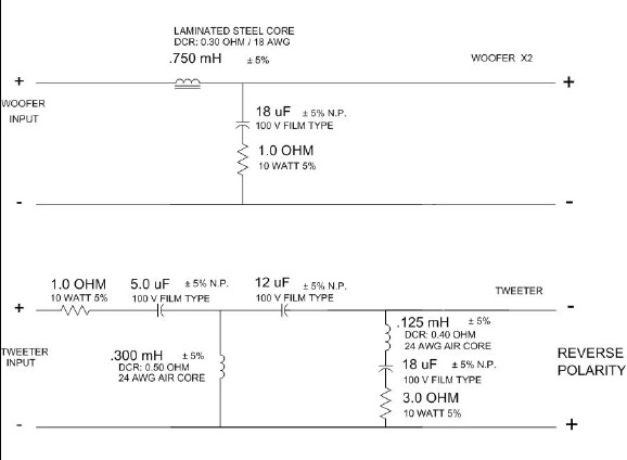
Here is the schematic:
comments on capacitor/inductor brand selection would be appreciated as well.
i don't currently have a budget for this project but i am always looking for good value.
I thought this might be a good way to approach my first loudspeaker project as i currently do not have the facilities to do any type of woodworking.
Also, I have read on other forums that rf-7 owners have obtained a significant improvement with same spec but higher quality part substitution. i think this is the approach i would like to take initially (i am open to being convinced otherwise).
Capacitor replacement seems simple enough but i am unsure of how to replace the inductors. i assume that higher quality inductors will have a lower resistance and change the filter profile. would changing the inductors require a crossover redesign?
Here are some pics of the crossover:
1 2 3 4
Here is the schematic:
comments on capacitor/inductor brand selection would be appreciated as well.
i don't currently have a budget for this project but i am always looking for good value.
Here is an air core inductor from Madisound (up in Madison, WI). If you look at the chart for the 16ga wound "Sidewinder"coils the 0.75mH coil has 0.29ohm DCR. I'm sure this will work fine in your application.
I am not sure how much improvement you will actually get from replacing the parts. They appear to be of a good quality.
Inductor replacement is the same as capacitors for as long as the value stays the same.
General understanding or believe is that higher gage inductors will perform better on the woofers, Such as 12 or 14 gage instead of 18. The difference may become apparent at higher volumes, IF.
Some people believe that copper or silver inductors such as this one
http://www.madisound.com/catalog/product_info.php?cPath=404_20_22&products_id=20
will perform better on the tweeter.
You could also change resistors for the none inductive type such as Mills or Eagle.
I would do 1 speaker at a time and then blind listen with a help of a friend to see if there’s any difference at all.
If you are retaining same values, crossover doesn’t have to be re-designed. .75mhz is .75mhz anyway you look at it. Then changing caps, go for higher voltage cups such as this.
http://www.madisound.com/catalog/index.php?cPath=404_5_11
Let us know how it worked out.
thank you for the replies.
my understanding is that changing out the iron core inductor in the low pass filter for an air core inductor will prevent distortion associated with core saturation. swapping in the inductor suggested by roddyama wouldn't change any other properties of the crossover because it has the same DCR (direct current resistance). seems like an easy choice.
the problem that i don't have a full handle on is the selection of lower guage inductors (as suggested by r-carpenter) as these inevitably have lower DCR. for example the inductor in the low pass filter has a DCR of .3 ohm, a lower guage inductor with the same inductance can have a DCR of about .05 ohm.
i am in the early stages of teaching myself how to model a crossover network so i am not sure of what effect a drop in DCR like the one mentioned above will have.
i know how to determine the impedance of the inductor as a function of frequency. i know how to calculate the corner frequency of a RC low pass filter. But i don't know how to generate an input output curve for a low pass filter with an inductor, let alone with a series resistor following the capacitor.
okapi said:the problem that i don't have a full handle on is the selection of lower guage inductors (as suggested by r-carpenter) as these inevitably have lower DCR. for example the inductor in the low pass filter has a DCR of .3 ohm, a lower guage inductor with the same inductance can have a DCR of about .05 ohm.
Just add a series resistor to make up the difference in the DCR. As an example, for the 0,125mH parallel coil shown in your schematic, start with the 20ga 0.15mH coil shown
here at the Madisound site. First get a rough count of the number of turns in the coil by counting the the turns across the width of the circumfrence and multiplying that by the number of layers. Than unwind about 17% of the turns and you'll be real close to 0.125mH. Or you can measure it if you have the means. For the resistance, just add a 0.3ohm 10W resistor in series with the other components in that parallel leg just before or just after the existing resistor.
For the 0.3mH coil, I'd go with the 19ga air core because it will be a bit easier to get a 0.2ohm resistor. Since this is just DCR, it can be placed inseries in that parallel leg with no effect on the response. Of course non-inductive resistors will be best but harder to get and more expensive.
I think you'll be pleased on how this will open up the sound of your speakers
As suggested, the only part worth playing with IMO is that steel core inductor. You have already indicated there is a certain amount of distortion associated with ferromagnetic core inductors. Core hysteresis will cause a certain amount of distortion, though the laminated steel core inductors used in this design will have low hysteresis at the frequencies in the low-pass section of this crossover. While distortion due to saturation is also possible, this would only occur at very high power levels (several hundred watts for most common inductor core sizes). I don't know if the distortion due to hysteresis will be audible in your application, but if you want to try any one thing, there is certainly the most possibility for improvement in this inductor. You may or may not want to add a series resistor to the inductor. Here are the reasons why.
Decreasing the resistance of the inductor will have two primary effects.
1. Altering the bass response of the woofers by changing the qts of the system. Typically this effect can be summed up as: lower series resistance, leaner (some would say tighter) bass; higher series resistance, more pronounced (some would say boomier) bass. Depending on your preference for bass alignments, you may like the more damped bass provided by a decrease in series resistance.
2. Altering the acoustic output across the range of the woofer by changing the resistive attenuation. This may manifest itself as a more prominent midrange due to the increased level of the woofer with respect to the tweeter. With such a small change in resistance as you are proposing, you will likely not notice the difference.
Changing the resistance of the inductor will not have an effect on the crossover frequency, as the filter effect is not a function of resistance (fixed regardless of frequency) but of impedance (changes with frequency).
The increasing impedance of an inductor with frequency is as you probably already know, the reason an inductor functions as a low pass filter. The impedance is the sum of the resistive and reactive components of the inductor at a given frequency.
At the 2200Hz crossover frequency, the impedance of the inductor will be:
Z=R+iX (ignore the i because we are only working with one complex impedance in this equation)
R = 0.30 Ohms
X = 2*pi*Frequency*Inductance
X = 2*pi*2200*0.75E-3
X = 10.37 Ohms
Z = 10.67 Ohms at 2200Hz
If you notice, the reactance of the inductor depends solely on the inductance value and frequency, thus the crossover filter frequency will rely solely on those values as well.
Note that in RLC circuits, the resistance value of the circuit determines the sharpness of the notch. In these circuits the sum of the inductor resistance and resistor value should be kept the same.
Added: The inductance of wirewound resistors is very small (see thread here for details) and should only be of any minor concern for large resistance values in series tweeter circuits.
Have fun with your project!
David
0H, here’s an idea. The changes that will be achieved from replacing these components will be minimal and probably not audible.
How about improving the cabinet itself first. May be some bracing?
How about improving the cabinet itself first. May be some bracing?
This is true. Some hearing aides have a very limited frequency response. 🙄R-Carpenter said:The changes that will be achieved from replacing these components will be minimal and probably not audible.
the plan
the responses have been great- exactly what i was looking for.
here is my tentative plan of action based on everyone's help.
all the changes i mention i will do one at a time so i can properly assess their effect.
i am going to change the inductor in the low pass filter with this inductor:
Goertz
for the following reasons:
1. the reduced DCR may result in a a little more midrange (and possibly bass??) - i find these speakers treble biased anyhow.
2. a possible increase in bass "tightness" (i find the bass on my speakers a little loose, i think this may be more amp/source related because i have heard both of my speakers [phase tech pc 3.1's] sound better with other upstream equipment, nevertheless i want to see if it will help).
3. possible reduction in distortion.
i may also try changing the resistor (with a non inductive type) and the cap in the low pass filter because their seems to be some difference of opinion on the possible outcome (none to some). i need to convince myself of the merits (or lack thereof) of boutique parts.
r-carpenter - your last comment has raised an issue that i would also like to consider. just this morning i had my hand on the cabinet assessing the vibration at high volume levels. obviously no vibration is better than some but i am not sure how much i can reasonably expect to reduce it. the cabinet already has two "windowpane" braces. i do have a vibration meter so i have the ability to quantitatively assess any changes.
along a similar line, when i had the crossover out i noticed that the foam dampening material was limited to a single large piece (2.5 to 3 inch thick) running from the bottom of the cabinet up to the base of the horn. the foam is not against the back of the cabinet but is up against the ports (2 of them), 6- 8 inches out from the back. This raises the question, could the speakers benefit from more or better placed stuffing? reducing the reflections would be the goal but i am also concerned about changing the tuning as I think i read somewhere on diyaudio that stuffing increases the cabinet volume.
once again, thanks for all the help. i will post the results and photos of the crossover mods here when i complete them.
roddyama said:
This is true. Some hearing aides have a very limited frequency response. 🙄
Don’t you doubt my hearing aid! The capacitors are Mundorf and the copper is oxygen free!😀
along a similar line, when i had the crossover out i noticed that the foam dampening material was limited to a single large piece (2.5 to 3 inch thick) running from the bottom of the cabinet up to the base of the horn. the foam is not against the back of the cabinet but is up against the ports (2 of them), 6- 8 inches out from the back. This raises the question, could the speakers benefit from more or better placed stuffing? reducing the reflections would be the goal but i am also concerned about changing the tuning as I think i read somewhere on diyaudio that stuffing increases the cabinet volume.
This concerns me, are you saying that the foam was covering the port entrances inside the cabinet? Perhaps you could take some pictures of the insides of the cabinet to allow for more constructive suggestions? If the foam was indeed blocking the ports, then I do not think it was intentional or optimal at all. (Unless they are using resistive ports, which would be unusual, but not unheard of)
I am a big fan of the Sonic Barrier type of cabinet damping material. This stuff does a good job of both absorbing sound inside the cabinet and damping vibrations on the cabinet walls. It is adhesive backed and easy to apply to surfaces inside the cabinet.
An externally hosted image should be here but it was not working when we last tested it.
As for the low pass inductor, I'm sure you meant the .75mH inductor not the .3mH inductor you linked to above. That looks like a good inductor. I don't buy into the whole foil is sonically superior deal, but it has low resistance and vacuum formed windings. Ignore claims about skin effect for the frequencies you are operating in. The price is a little steep, and as you mentioned that you are value oriented I feel obligated to show you a value alternative. I find Erse inductors, particularly the ones sold by Zalytron to be an extremely good value. Zalytron has the lowest prices I've found, and the quality of the Erse inductors I have purchased have been very good. The 14 AWG Air core Erse inductor has ever so slightly more resistance than the 12 AWG foil inductor (.181ohms vs .105ohms) but it costs nearly a quarter of what the Goertz costs ($10.40 vs. $39.10). I just spent alot of money on crossover parts for a 4 way design, and I used Erse inductors from Zalytron.
Of course, if you are already placing an order from another place that carries 14AWG air core inductors, it might make more sense to order there and only pay one shipping fee. I wish you could still get North Creek inductors. They had 8AWG inductors!
quick cabinet pics before work
these are some quick shots of the cabinet so i can keep up with the discussion. there are two 1" inch thick pieces of foam. the lower piece runs along the bottom of the cabinet from the back, about half way along the bottom it bends upwards and passes in front of the ports. it ends at the window brace. the second piece runs along the window brace from the back of the cabinet and bends up at the brace end. the second piece ends at the top of the cabinet. there is a gap between the two pieces of foam that would allow some air direct access to the ports. tonight i will do a profile drawing of the speaker to give a better idea of the foam placement.
photo of opening with lower driver removed
looking up through opening
looking up between top piece of foam and top driver and horn.
straight shot with bottom foam removed
down shot with bottom foam removed
foam profile
the foam is 1" thick not the 2-3" i mentioned earlier- sorry for the mistake.
gtforme00- thanks for catching my mistake, i will try the inductors you suggest.
cabinet construction notes: looks like cabinet sides, back and top are all 3/4" plywood. baffle and braces are mdf. there is only one brace despite what the specs say.
I did a little snooping for more information on these and have found a reference on the klipsch forum who states that mutual inductance (the interaction between two inductors) was factored in to the design of these speakers. Thus changing the coil to a different coil or moving the coil from its factory position will have an effect on the inductance of the affected inductors.
The same source also claims that lowering the resistance in the tweeter notch circuit helps to remove some sibilance from the treble, making the midrange and bass sound more prominent.
This user is DeanG on the Klipsch forum. He seems to have alot of experience upgrading the RF-7 crossovers. I would talk to him before making changes, as his upgrades seem generally well reviewed.
As far as the cabinet goes, it looks like a prime candidate for some additional damping. I would use the sonic barrier I linked to above and line the walls, particularly near the woofers. Thin fiberglass insulation also functions as an excellent absorption material, and is very inexpensive. The sonic barrier has the extra effect of mass loading the cabinet walls to reduce resonances.
Because you are working with a ported enclosure, it would be best to limit any damping materials to covering the walls only (as opposed to stuffing the cabinet with loose material). This will avoid altering the box tuning too much.
The same source also claims that lowering the resistance in the tweeter notch circuit helps to remove some sibilance from the treble, making the midrange and bass sound more prominent.
I've never seen an RF-7 network with a 3 ohm resistor in the notch circuit - interesting. I've lost count of how many I've done, but they've always been 2 ohms. I lower the value to 1.66 ohms.
This user is DeanG on the Klipsch forum. He seems to have alot of experience upgrading the RF-7 crossovers. I would talk to him before making changes, as his upgrades seem generally well reviewed.
As far as the cabinet goes, it looks like a prime candidate for some additional damping. I would use the sonic barrier I linked to above and line the walls, particularly near the woofers. Thin fiberglass insulation also functions as an excellent absorption material, and is very inexpensive. The sonic barrier has the extra effect of mass loading the cabinet walls to reduce resonances.
Because you are working with a ported enclosure, it would be best to limit any damping materials to covering the walls only (as opposed to stuffing the cabinet with loose material). This will avoid altering the box tuning too much.
gtforme00 said:I did a little snooping for more information on these and have found a reference on the klipsch forum who states that mutual inductance (the interaction between two inductors) was factored in to the design of these speakers. Thus changing the coil to a different coil or moving the coil from its factory position will have an effect on the inductance of the affected inductors.
i assume this applies to the high pass filter as the low pass only has a single inductor?
gtforme00 said:The same source also claims that lowering the resistance in the tweeter notch circuit helps to remove some sibilance from the treble, making the midrange and bass sound more prominent.
[/B]
DeanG is definitely right. the schematic (provided by klipsch) does not match the resistor value in my crossover (see attached photo #3 in post 1).
sibilance is definitely a problem i experience. does this result from resonance in the throat of the horn? i was going to try to experiment with some mass damping around the base of the horn. i will also try DeanG suggestion of lowering the notch resistor value.
gtforme00 said:This user is DeanG on the Klipsch forum. He seems to have alot of experience upgrading the RF-7 crossovers. I would talk to him before making changes, as his upgrades seem generally well reviewed.
[/B]
i will definitely contact DeanG now. i had spent some time on the klipsch forum and was aware that he was selling crossover upgrades but i was not sure if he was willing to freely give advice. I also found the search engine lacking - it was very time consuming finding the relevant posts.
gtforme00 said:As far as the cabinet goes, it looks like a prime candidate for some additional damping. I would use the sonic barrier I linked to above and line the walls, particularly near the woofers. Thin fiberglass insulation also functions as an excellent absorption material, and is very inexpensive. The sonic barrier has the extra effect of mass loading the cabinet walls to reduce resonances.
Because you are working with a ported enclosure, it would be best to limit any damping materials to covering the walls only (as opposed to stuffing the cabinet with loose material). This will avoid altering the box tuning too much.
[/B]
i will try some of the sonic barrier on the walls adjacent to the woofers. what are you thoughts on the back wall and foam covering the ports? should i cover the back wall with sonic barrier leaving the ports open?
although i don't have access to a wood shop i do have have access to a metal shop so i could make another brace if people think this will help. tonight, if i have time, i will make a cabinet vibration vs. frequency plot.
You are certainly right, the mutual inductance should only apply to the tweeter circuit.
I have not found a good explanation yet to tell me why one film capacitor should sound better than another. The capacitors in your pictures look as good as any I have put in my amplifiers, and I have measured exceedingly low distortion from those amplifiers. To pacify the subjectivists, I have not heard a difference that would indicate better performance either, though I have only strayed as far as Axon capacitors before my good senses returned.
I think you are on the right track towards rationally improving the quality of your speakers. Good absorption material and better quality woofer inductors seem like the best bang for the buck in the RF-7.
As far as the absorption materials, here's a rundown.
You ideally want to just line the walls in a ported enclosure, especially large parallel walls like the sides. The thicker the insulation, the lower frequency it will absorb, though practicality limits most materials to an inch or so thick. The back of the enclosure directly behind the woofers will also benefit from a good absorptive layer. I would run this just down to the top of the ports, not going past them and especially not covering them. The front baffle opposing the ports could benefit from a layer of absorption material, provided you leave generous room in front of the ports.
There are three common absorption materials: Foams, fiberglass, and polyester batting.
Foams come in adhesive backed and non-adhesive backed types. i prefer the adhesive backed because I have grown to hate messy adhesive sprays. The sonic barrier with the mass loaded layer claims to be best on large expanses of panel that tend to vibrate, ie the side panels. Go ahead and do your vibration experiment, and if the vibration concerns you it certainly could help to use the sonic barrier. If you use sonic barrier I would use the mass loaded type on the sides of the enclosure and the plain foam type on the rear of the enclosure.
Fiberglass insulation is a great absorber of sound. As far as absorption performance alone goes, it probably outperforms even sonic barrier. However, you don't get the panel damping effect with the fiberglass. Some people express concern that the fibers can escape the ports and float out into the room, I can't say I've experienced this, but if this is a concern to you, you might want to stick with foams or polyester batting as absorption materials. Fiberglass is certainly less expensive than foam and is the value winner. You will unfortunately have to deal with adhesive spray to adhere the paper backing to the cabinet wall. Just don't get any of the spray on cloth you don't want ruined.
I have been the least impressed with polyester batting as an absorber. I just don't think it is dense enough to give comparable attenuation to the foams and fiberglass. It may be good for increasing the apparent volume of an enclosure, but I do not recommend it for sound absorption.
That's all for now, I look forward to your vibration test results.
Regards,
David
I agree with David. That foam doesn’t look like it’s doing much of anything. I’d Sonic Barrier the sides and add some polyfill to compensate for the lost volume. Just keep polyfill away from the drivers and port openings.
vibration measurement
Here is a plot of side panel vibration amplitude as a function of frequency:
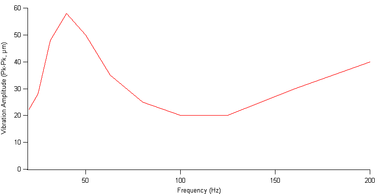
This has not been normalized to SPL but it will still serve as a baseline on which to assess the changes i make.
measurement was taken with IEM Corp vibration meter Model PAL150 (Atlanta, Georgia).
bass Decade 1/3-octave warble tones were taken from Stereophile test CD2
I did some more looking around on the klipsch forum and here is what DeanG had to say about the inductor in the woofer circuit:
"In the woofer circuit, the DCR of the coil is used to align the driver, port, and cabinet. So, leave it alone."
i could still switch out the inductor for an air core with the same DCR. but would reducing DCR to 0.1 ohm from 0.3 ohm really misalign the driver, port, and cabinet - that sounds bad. i find this hard to reconcile with David's (gtforme00) comments on a reduced DCR which as far as i can tell would lead either undetectable or minimal positive changes.
Updated plan.
phase 1. order non inductive resistors, and reduce resistance in the notch filter of the tweeter. this is easy and inexpensive so i will try this first.
phase 2. get sonic barrier and place according gtforme00 instructions. use fiberglass to compensate for lost volume. I don't suppose there is a formula for estimating volume increase per oz of fiberglass used? thinking about this a little more, the volume loss may not be that much since i am replacing the existing foam.
phase 3. try a different inductor in the woofer low pass filter.
somewhere in the distant future i may try some other caps but that will have to wait for now.
thanks again.
Tim
Here is a plot of side panel vibration amplitude as a function of frequency:
This has not been normalized to SPL but it will still serve as a baseline on which to assess the changes i make.
measurement was taken with IEM Corp vibration meter Model PAL150 (Atlanta, Georgia).
bass Decade 1/3-octave warble tones were taken from Stereophile test CD2
I did some more looking around on the klipsch forum and here is what DeanG had to say about the inductor in the woofer circuit:
"In the woofer circuit, the DCR of the coil is used to align the driver, port, and cabinet. So, leave it alone."
i could still switch out the inductor for an air core with the same DCR. but would reducing DCR to 0.1 ohm from 0.3 ohm really misalign the driver, port, and cabinet - that sounds bad. i find this hard to reconcile with David's (gtforme00) comments on a reduced DCR which as far as i can tell would lead either undetectable or minimal positive changes.
Updated plan.
phase 1. order non inductive resistors, and reduce resistance in the notch filter of the tweeter. this is easy and inexpensive so i will try this first.
phase 2. get sonic barrier and place according gtforme00 instructions. use fiberglass to compensate for lost volume. I don't suppose there is a formula for estimating volume increase per oz of fiberglass used? thinking about this a little more, the volume loss may not be that much since i am replacing the existing foam.
phase 3. try a different inductor in the woofer low pass filter.
somewhere in the distant future i may try some other caps but that will have to wait for now.
thanks again.
Tim
sonic barrier
according to the sonic barrier description on parts express it causes an "increase apparent enclosure volume"
are they saying that it does not reduce the volume as much as you would expect from its dimensions? or are they saying that if you add sonic barrier and want to keep the effective volume the same you would need to add something to the inside of the cabinet to take up space?
sorry for the confusion.
Tim
It is not hard at all to reconcile the statements regarding the inductor resistance. Yes, the inductor resistance is factored in to a design. Changing the value of a series resistance will affect the alignment of a speaker in a box. Both DeanG and I have said exactly that. Previously I said that lowering the resistance would serve to "lean out" the bass. This is still true. As is the statement about helping boost the overall woofer output. Changing the resistance of the inductor will not change the tuning frequency of the box. The volume of the box and the port dimensions alone affect the box tuning frequency. Changing the resistance of the inductor will however affect the woofer characteristics and thus the woofer response in a box. In this respect alone it will change the "alignment" of the driver, port, and cabinet. The changes will be what I described to you earlier.
Let me try to explain further how the series resistance effects the woofer response in a box.
When you look at thiele-small parameters of a woofer, you will see several "q" parameters. These each indicate the tendency of a woofer to resonate at its natural frequency. The higher the q, the more tendency the woofer has to resonate at that frequency. There are mechanical and electrical parameters that contribute to this tendency, but the two parameters(qms and qes respectively) are combined in the "qts" parameter, which indicates the overall tendency of the woofer to resonate at its natural frequency.
If we put a woofer in a box, the woofer mechanical suspension will combine with the tendency of the air in the box to act as a spring, resulting in a new resonant frequency and new tendency to resonate. Lets call this tendency the total system q, or "qtc".
Now, because qtc is a function of qts, which is in turn a function of qes, any changes to qes will be translated down to qtc, or simply speaking; any changes in the electrical tendency to resonate will be propagated down to the tendency of the overall system to resonate. This is where altering the series resistance comes in. By changing the series resistance to a lower resistance, we are reducing the tendency of the woofer to resonate, thus lowing the total system tendency of the woofer to resonate. This can be subjectively described as leaner bass.
The ported part of the enclosure responds to the woofers tendency to resonate. The woofer simply excites the air volume which by virtue of the port has its own tendency to resonate. Thus, lowering the tendency of the woofer to resonate by lowering the series resistance will also lower the tendency of the air mass to resonate, but will not affect the fundamental frequency at which it will tend to resonate.
I hope you could follow all of the above, it can get way more complicated and I glossed over the details, but you should be able to understand now how DeanG and I are not contradicting each other about the series resistance of the woofer.
If you are very concerned with the bass alignment, you can measure the system q with some rather simple equipment (at maximum a few resistors, a multimeter, and a computer soundcard to generate signals), and then tweak it to taste.
- Status
- Not open for further replies.
- Home
- Loudspeakers
- Multi-Way
- First (Noob) crossover project - upgrade klipsch RF-7