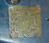
Some updates:
Prompted by another member I am posting the changes I've made to the all-in-one jig. The version shown earlier has a flaw and should NOT be used.
I have a revised schematic:
View attachment ALL_IN_ONE_JIG_SCH.pdf
It is designed with a single board layout in mind:
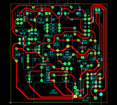
It has board mounted standard 3.5mm phono jacks and is powered by an AC wall wart. I have the prototype mocked up but I'm waiting on the switches - especially the 4PDT before I stick it in a small enclosure.
Should be sweet!
Prompted by another member I am posting the changes I've made to the all-in-one jig. The version shown earlier has a flaw and should NOT be used.
I have a revised schematic:
View attachment ALL_IN_ONE_JIG_SCH.pdf
It is designed with a single board layout in mind:

It has board mounted standard 3.5mm phono jacks and is powered by an AC wall wart. I have the prototype mocked up but I'm waiting on the switches - especially the 4PDT before I stick it in a small enclosure.
Should be sweet!
The All In One is not all in one anymore - the microphone preamp is now separate. I have built a new mic and it has the preamp enclosed:
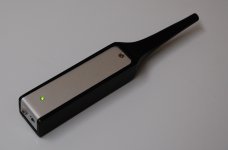
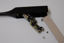
It uses the LM6132 and I expect the 9 volt battery will need to be changed from old age rather than drain. It has a low (10db) gain setting and a high (21db) setting, selectable with the switch.
I modified the electret cartridge as suggested by Linkwitz successfully and it works very well, though I didn't notice a difference with the response tests I did.
Last edited:
A few good reasons to leave the mic preamp out, amongst those is my desire to use the jig to test amplifiers - I will build an attenuator that connects the amplifier to the mic input on the all in one jig. This simplifies things quite a bit.
The jig is nearing completion:
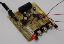
I received the switch I needed and got it up and running. Works like a charm.
Here i have the front panel done. It is an etched copper clad board, cleaned and sprayed with clear lacquer to prevent tarnish.
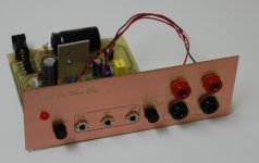
I think it looks cool.
Nice to light it up:
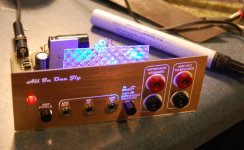
The box it lives in is being painted and should be ready for action in a couple days.
The jig is nearing completion:

I received the switch I needed and got it up and running. Works like a charm.
Here i have the front panel done. It is an etched copper clad board, cleaned and sprayed with clear lacquer to prevent tarnish.

I think it looks cool.
Nice to light it up:

The box it lives in is being painted and should be ready for action in a couple days.
Beautiful work as always, John. Did you etch the boards?
Thanks!
Yes, I etched both the circuit board and the front panel board. I've been wanting to use this idea for a while (PCB front panel) and saw this as the perfect project to do it.
Would you mind share your PCB design?
I'll post the layout in .pdf soon (for those that can etch their own) or you can email me for the Gerbers, but give it some time - I don't have the board configured for export to RS-274X yet (some drill sizes to change, etc.). The board uses specific parts too, like the 3.5mm jacks and the switches so an accurate BOM would need to be put together.
Hi WT,
The switch is THIS one. All of the components are fairly inexpensive - the wall wart was ~$8.00 (12VAC, 1amp).
OK, I'm done. Box is painted and dried:
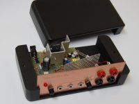
The front panel slips into slots in the box.
A closer look inside:
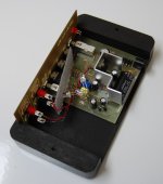
The LEDs were an after though and I just rigged up a simple rectifier on an open part of the board. The LEDs are running at around 10mA, so not full brightness. The bezel is cut from a broken fluorescent light fixture and is stuck in place with 2 small spots of duct seal. I may get ambitious in the future and change the internal lighting but this will do for now.
And here it is together and all lit up:
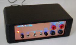
Ready for action.

The switch is THIS one. All of the components are fairly inexpensive - the wall wart was ~$8.00 (12VAC, 1amp).
OK, I'm done. Box is painted and dried:

The front panel slips into slots in the box.
A closer look inside:

The LEDs were an after though and I just rigged up a simple rectifier on an open part of the board. The LEDs are running at around 10mA, so not full brightness. The bezel is cut from a broken fluorescent light fixture and is stuck in place with 2 small spots of duct seal. I may get ambitious in the future and change the internal lighting but this will do for now.
And here it is together and all lit up:

Ready for action.
Very nice!
...offer some boards? including the faceplate?
Thanks Ed,
It depends on how many are interested. I've had a couple members ask about it and also a few who have asked about the mic. I would be open to the idea, possibly even a short kit form with the specific parts included (jacks, switches) and enclosure for those that are interested.
I have updated the schematic, mainly to delete the dual grounds - this was a bad idea and not really needed:
View attachment ALL_IN_ONE_JIG_SCH.pdf
I would be interested........
Well, that's a start.
I'll see what I can come up with.
It was bugging me how I mounted the chipamp near the centre of the board, so I took a few minutes to relocate it to the back of the board. This way it can be attached to the rear of the box for heat sinking.
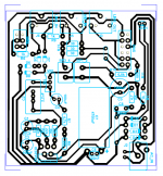
The pdf of the copper bottom is coming soon.
Another revision, moved some traces and added a bypass cap at the AC in:
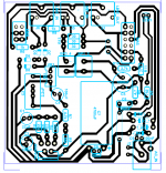
I've been using the one I've built to do some frequency response tests. I set the amp to output 2.83Vrms by adjusting VR1 while the sine signal was playing from Speaker Workshop with no load. This is 1 watt into 8 ohms but wow, was it loud! It startled me a bit when I ran the test.
I also gave Holm Impulse a try and that program is nice too - easy to use but lacks most of the functionality of SW.
It's stunning just how accurate SW is for measuring passive components. I measured a bunch of power resistors - .1 ohm, .33 ohm, etc and it was dead on (within the tolerance of the part). Caps and inductors with the ability to measure inductance being a huge bonus, it was bang on.
I would be interested........
I think there will be a LOT of interest in this..
ummmmmm like from me...
Mark
I'd be interested in a board if you're getting a batch done. If not the Gerbers would be great if possible when you're happy with them, and I'll get one made here.
I was searching for just such a jig design when I found this thread so am very pleased as it saves me a lot of work.
Cheers
I was searching for just such a jig design when I found this thread so am very pleased as it saves me a lot of work.
Cheers
I would order one also
Plus it would be nice to have alternatives like a pot for fine tuning the gain level and output to the speakers.
I was thing of putting a 10k pot to be able to adjust or down up the feed back resistor loop to to the mic pre amp op amp and if there are any better amp
Plus it would be nice to have alternatives like a pot for fine tuning the gain level and output to the speakers.
I was thing of putting a 10k pot to be able to adjust or down up the feed back resistor loop to to the mic pre amp op amp and if there are any better amp
Plus it would be nice to have alternatives like a pot for fine tuning the gain level and output to the speakers.
I was thing of putting a 10k pot to be able to adjust or down up the feed back resistor loop to to the mic pre amp op amp and if there are any better amp
It has a level setting pot on the board (see schematic).
If you mean better than the TDA2030, the board will straight up take an LM1875 without a problem - they are the same pin out. In fact, that's what is in the one I'm using.
This jig is mean to be used with a mic with a separate preamp, or one like mine - it has the preamp inside:
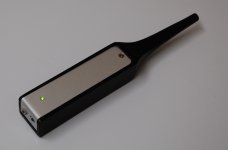
I re-did it that way in order to use the jig to test amps through an attenuator (that I'll get to eventually). Having the mic preamp in the jig was a good idea but puts too many limitations on its functionality.
- Status
- This old topic is closed. If you want to reopen this topic, contact a moderator using the "Report Post" button.
- Home
- Loudspeakers
- Multi-Way
- Re-Jigging the jig: Speaker testing device for Arta, Speaker Workshop & HOLMImpulse

