I am sooooooooo happy I have found this thread right now!!!
I am about to jump to DIY for one project, but i)I am a real newbie in electronics, ii)I do not plan to do a lot of projects in the future.
I have ordered a Wallin Mic Preamp PCB from Vikash at Madaboutsound and was looking into components for the Wallin jig or Claudio's cables without being able to make a decision for either solution... Eric's jig looks a bit complicated to me and I found Claudio's set up a bit confusing for a newbie like me and possibly dangerous for the SC as well... maybe this one falls just in the (good) middle.
I do not want to have everything in one box, just looking for the jig.
If I may, I have a few questions and I hope there are still people following this topic...
Shall I then ?.... Thanks!")
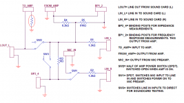
1) What have you lost (features) with losing the 4R and 16R calibration resistor ? I was never clear from Claudio's pages where calibration was taking place.
2) If I read the diagram correctly, there are 1.2k resistors on the pass of lines IN (from the mic preamp and in loop mode as well). Why is that ? Do you need to tell SW anything about this ? (you see, real newbie here)
3) Again, provided I understand correctly, the FROM_AMP is coming from the amp speakers binding posts isn't it ?
4) In loop mode, SW1 remains as it is and SW3 is closed ?
5) For impedence measurement, you would connect your "device" to BP3_4. I am unsure about the switch positions... I would guess SW3 and SW1 stays as they are in the diagram. Again, I do not understand why the signal goes thru the 8R before going to the device. Isn't it going to change the measure ?
6) For measure of frequency reponse and phase, you connect (your amp input to TO_AMP, your amp speaker posts to FROM_AMP), your "device" to test to BP1_2, your mic preamp output to... MIC_IN and you would "flip"SW1...
7) I assume that for NTF measure, you would connecte everithing like the above except the the device is now filter + speakers and you would connect alternatively each speaker directly in parallel to the mic preamp input (or BP3_4 with SW3 closed ?)
8) I assume that R4 and R5 are "high power" (5W, 10W ?) but the rest are traditional 1/4W.
I know this is a lot of question, and I would be eternally gratefull (well...) if someone replies.
Many thanks in advance (trully).
PS : Actually, as I assume I am not the only newbie in the world, that would be really really really great to have a schematic with connections and switch positions for each SW measurement situation...
I am about to jump to DIY for one project, but i)I am a real newbie in electronics, ii)I do not plan to do a lot of projects in the future.
I have ordered a Wallin Mic Preamp PCB from Vikash at Madaboutsound and was looking into components for the Wallin jig or Claudio's cables without being able to make a decision for either solution... Eric's jig looks a bit complicated to me and I found Claudio's set up a bit confusing for a newbie like me and possibly dangerous for the SC as well... maybe this one falls just in the (good) middle.
I do not want to have everything in one box, just looking for the jig.
If I may, I have a few questions and I hope there are still people following this topic...
Shall I then ?.... Thanks!
1) What have you lost (features) with losing the 4R and 16R calibration resistor ? I was never clear from Claudio's pages where calibration was taking place.
2) If I read the diagram correctly, there are 1.2k resistors on the pass of lines IN (from the mic preamp and in loop mode as well). Why is that ? Do you need to tell SW anything about this ? (you see, real newbie here)
3) Again, provided I understand correctly, the FROM_AMP is coming from the amp speakers binding posts isn't it ?
4) In loop mode, SW1 remains as it is and SW3 is closed ?
5) For impedence measurement, you would connect your "device" to BP3_4. I am unsure about the switch positions... I would guess SW3 and SW1 stays as they are in the diagram. Again, I do not understand why the signal goes thru the 8R before going to the device. Isn't it going to change the measure ?
6) For measure of frequency reponse and phase, you connect (your amp input to TO_AMP, your amp speaker posts to FROM_AMP), your "device" to test to BP1_2, your mic preamp output to... MIC_IN and you would "flip"SW1...
7) I assume that for NTF measure, you would connecte everithing like the above except the the device is now filter + speakers and you would connect alternatively each speaker directly in parallel to the mic preamp input (or BP3_4 with SW3 closed ?)
8) I assume that R4 and R5 are "high power" (5W, 10W ?) but the rest are traditional 1/4W.
I know this is a lot of question, and I would be eternally gratefull (well...) if someone replies.
Many thanks in advance (trully).
PS : Actually, as I assume I am not the only newbie in the world, that would be really really really great to have a schematic with connections and switch positions for each SW measurement situation...
jm_kzo said:I am sooooooooo happy I have found this thread right now!!!
I am about to jump to DIY for one project, but i)I am a real newbie in electronics, ii)I do not plan to do a lot of projects in the future.
I have ordered a Wallin Mic Preamp PCB from Vikash at Madaboutsound and was looking into components for the Wallin jig or Claudio's cables without being able to make a decision for either solution... Eric's jig looks a bit complicated to me and I found Claudio's set up a bit confusing for a newbie like me and possibly dangerous for the SC as well... maybe this one falls just in the (good) middle.
I do not want to have everything in one box, just looking for the jig.
If I may, I have a few questions and I hope there are still people following this topic...
Shall I then ?.... Thanks!
1) What have you lost (features) with losing the 4R and 16R calibration resistor ? I was never clear from Claudio's pages where calibration was taking place.
2) If I read the diagram correctly, there are 1.2k resistors on the pass of lines IN (from the mic preamp and in loop mode as well). Why is that ? Do you need to tell SW anything about this ? (you see, real newbie here)
3) Again, provided I understand correctly, the FROM_AMP is coming from the amp speakers binding posts isn't it ?
4) In loop mode, SW1 remains as it is and SW3 is closed ?
5) For impedence measurement, you would connect your "device" to BP3_4. I am unsure about the switch positions... I would guess SW3 and SW1 stays as they are in the diagram. Again, I do not understand why the signal goes thru the 8R before going to the device. Isn't it going to change the measure ?
6) For measure of frequency reponse and phase, you connect (your amp input to TO_AMP, your amp speaker posts to FROM_AMP), your "device" to test to BP1_2, your mic preamp output to... MIC_IN and you would "flip"SW1...
7) I assume that for NTF measure, you would connecte everithing like the above except the the device is now filter + speakers and you would connect alternatively each speaker directly in parallel to the mic preamp input (or BP3_4 with SW3 closed ?)
8) I assume that R4 and R5 are "high power" (5W, 10W ?) but the rest are traditional 1/4W.
I know this is a lot of question, and I would be eternally gratefull (well...) if someone replies.
Many thanks in advance (trully).
PS : Actually, as I assume I am not the only newbie in the world, that would be really really really great to have a schematic with connections and switch positions for each SW measurement situation...
If you want something simpler, this one was designed to work with SoundEasy, but I assume they all use the same principles.
Hi,
I pretty much forgot about this thread...
For calibration, I use loose resistors clipped to the leads from BP3 and 4. This puts them in circuit without the complexity of switches.
These are limiting resistors and are important, but make no difference as far as calibration goes.
Yes, it's the output from the amp. In my case, it is from the chipamp board.
Yes, SW3 connects the left and right line input of the soundcard to the left line out on the soundcard.
The 8 ohm resistor is for reference between channels. It will not change the measurement. Once setup, SW will give very accurate measurements of speaker impedance and also passive components, such as resistors, capacitors and very valuable - inductors.
Correct.
A question for you - what is NTF? I'm a little lost on this one.
Not really that powerful for R4 and R5. Output from the amp needs to be kept low anyway. My recommendation is to build the LM3886 amp I designed, especially for this jig. It has limited gain and low voltage, so the chances of burning up your soundcard is minimized. If you would like the schematic and board layout, I could post it here.
I pretty much forgot about this thread...
jm_kzo said:
If I may, I have a few questions and I hope there are still people following this topic...
1) What have you lost (features) with losing the 4R and 16R calibration resistor ? I was never clear from Claudio's pages where calibration was taking place.
For calibration, I use loose resistors clipped to the leads from BP3 and 4. This puts them in circuit without the complexity of switches.
jm_kzo said:
2) If I read the diagram correctly, there are 1.2k resistors on the pass of lines IN (from the mic preamp and in loop mode as well). Why is that ? Do you need to tell SW anything about this ? (you see, real newbie here)
These are limiting resistors and are important, but make no difference as far as calibration goes.
jm_kzo said:
3) Again, provided I understand correctly, the FROM_AMP is coming from the amp speakers binding posts isn't it ?
Yes, it's the output from the amp. In my case, it is from the chipamp board.
jm_kzo said:
4) In loop mode, SW1 remains as it is and SW3 is closed ?
Yes, SW3 connects the left and right line input of the soundcard to the left line out on the soundcard.
jm_kzo said:
5) For impedence measurement, you would connect your "device" to BP3_4. I am unsure about the switch positions... I would guess SW3 and SW1 stays as they are in the diagram. Again, I do not understand why the signal goes thru the 8R before going to the device. Isn't it going to change the measure ?
The 8 ohm resistor is for reference between channels. It will not change the measurement. Once setup, SW will give very accurate measurements of speaker impedance and also passive components, such as resistors, capacitors and very valuable - inductors.
jm_kzo said:
6) For measure of frequency reponse and phase, you connect (your amp input to TO_AMP, your amp speaker posts to FROM_AMP), your "device" to test to BP1_2, your mic preamp output to... MIC_IN and you would "flip"SW1...
Correct.
jm_kzo said:
7) I assume that for NTF measure, you would connecte everithing like the above except the the device is now filter + speakers and you would connect alternatively each speaker directly in parallel to the mic preamp input (or BP3_4 with SW3 closed ?)
A question for you - what is NTF? I'm a little lost on this one.
jm_kzo said:
8) I assume that R4 and R5 are "high power" (5W, 10W ?) but the rest are traditional 1/4W.
Not really that powerful for R4 and R5. Output from the amp needs to be kept low anyway. My recommendation is to build the LM3886 amp I designed, especially for this jig. It has limited gain and low voltage, so the chances of burning up your soundcard is minimized. If you would like the schematic and board layout, I could post it here.
Attachments
Hi John, many thanks for your answers.
NTF stands for Network Transfer Function (http://www.claudionegro.com/swntf/swntf.html). If I understand correctly, this will measure what goes in the filter compared to what goes in the driver.
In the schematic of your jig all grounds are actually physically connected together aren't they ?
Thanks again for your help.
That's funny.
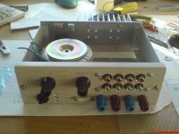
I've just started a similar project.
Here's my small progress so far:
http://kofoedmejer.squarespace.com/pics/kofoedmejerjig/
I'll base my work on Eric Wallins work but try to make a better UI.
I'll also integrate a stereo-amp to use in the desktop system when not measuring speakers.
Regards TroelsM
Attachments
jm_kzo said:Another step towards simplicity!!!
Just to make sure I read this correctly, for the RCAs that connects to the SC Line IN, the hot spot is connected to the ground by a 22k Resistor ?
Correct.
This thread is interesting, I think I'll stick with it more.
Originally I had thought about it, but I was concerned about noise. Especially the power amp section against the mic preamp. I was also wondering how the mic cable capacitance would effect mic performance. I started out with cheap plasic chassis for everything, and now gradually switching to metal chassis.
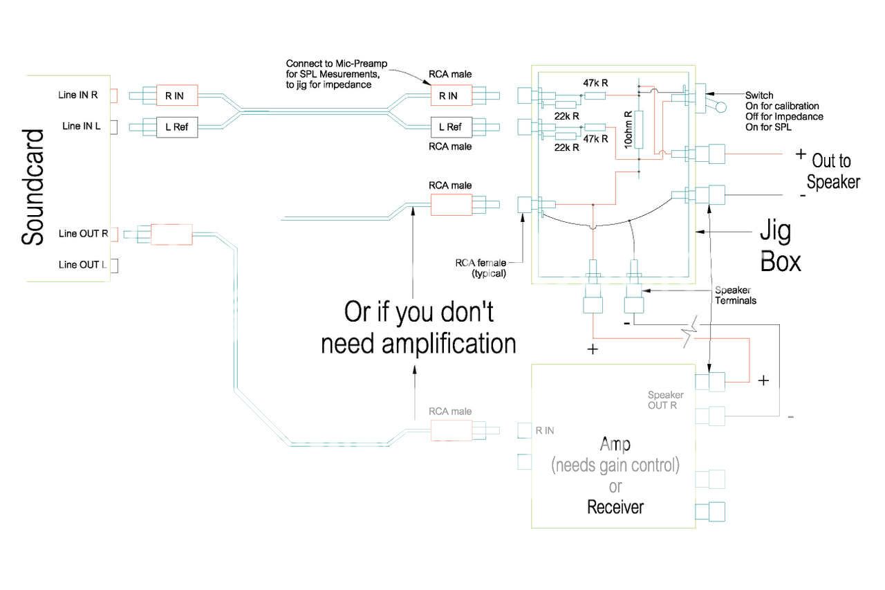
Below is something close to what I currently use as a jig design.
Normally, I would assume 3V rms for max SC input and output unless I know the specs on the sound card. This seems to have worked with many computers.
The input attenuator so that control of how much driver to the speaker is provided.
The output attenuator assures that no matter what level of power you select, the SC input is never overloaded so as to protect the SC.
Originally I had thought about it, but I was concerned about noise. Especially the power amp section against the mic preamp. I was also wondering how the mic cable capacitance would effect mic performance. I started out with cheap plasic chassis for everything, and now gradually switching to metal chassis.
Below is something close to what I currently use as a jig design.
Normally, I would assume 3V rms for max SC input and output unless I know the specs on the sound card. This seems to have worked with many computers.
The input attenuator so that control of how much driver to the speaker is provided.
The output attenuator assures that no matter what level of power you select, the SC input is never overloaded so as to protect the SC.
forgot the pic.soongsc said:This thread is interesting, I think I'll stick with it more.
Originally I had thought about it, but I was concerned about noise. Especially the power amp section against the mic preamp. I was also wondering how the mic cable capacitance would effect mic performance. I started out with cheap plasic chassis for everything, and now gradually switching to metal chassis.
Below is something close to what I currently use as a jig design.
Normally, I would assume 3V rms for max SC input and output unless I know the specs on the sound card. This seems to have worked with many computers.
The input attenuator so that control of how much driver to the speaker is provided.
The output attenuator assures that no matter what level of power you select, the SC input is never overloaded so as to protect the SC.
Attachments
454Casull said:MJL, the - output from the amp in your schematic goes to ground. What if the - of the amp isn't at the same potential as its own ground (signal, power)?
Also, when jumping BP3_4 with a calibration resistor, do all the other connections need to be disconnected?
Hi 454,
Sorry for the delay.
I used the ground symbol in the schematic as a handy way to show things and to simplify. In my version of this jig, all of the grounds do tie together, but input ground to the amp has a 10 ohm resistor for isolation - see revised schematic below.
When I use the calibration resistors, nothing gets disconnected, I just switch to "direct" and follow the calibration procedure.
Hope that helps.
Attachments
Oy, thanks for the response. I decided to go with Claudio's cables, though.
I ran into a problem doing his volume setup. When I output a sine signal, the input windows show square waves. I thought it might be severe clipping, but when I reduce either the output or the input volumes, beyond a certain point, the square waves suddenly disappear, and nothing shows up on the inputs (except some noise...?)
Did I really screw up the cables, or is my sound card bad?
- Status
- This old topic is closed. If you want to reopen this topic, contact a moderator using the "Report Post" button.
- Home
- Loudspeakers
- Multi-Way
- Re-Jigging the jig: Speaker testing device for Arta, Speaker Workshop & HOLMImpulse