Thank you all for the valuable input, what you say sounds interesting. Room is average, rather mid-size, but I'll move soon to a new one with plenty space for everything. Speaker size and placement is not an issue. ...
Back to topic: 2 speakers in series halves excursion (we can say halves power falling onto 1 speaker if they're identical). This website's calculator tells thr same for parallel connected speakers too which in my opinion is not the case. In parallel connection I think both individual speakers retain their power and excursion. ...
In Parallel each speaker gets half the power in the sense that if 2 amps are drawn from the AMP, then 1 amp goes to each speaker. But if we consider just the speakers, they both get the same power ... 1 amp each.
Also, consider that Power and Voltage are not linear, there is a SQUARE function in their -
P = E^2 / R
If we have two speakers in Series and we apply a 10v signal, then each speaker gets 5 volts.
P1 = 10^2 / 8 = 12.52w
But each speaker gets half the voltage, so that's 5 volts each.
P2 = 5^2 / 8 = 3.125w
Keep in mind that the power went down because the Impedance went up and therefore the Current went down.
Slightly unrealistic but if we feed a single driver 10 AMPS and a pair of Series Drivers 10 AMPS then we have -
P = I^2 x R
P1 = 100 x 8 = 800w
But, in Series both speakers get the same Current, though they only get half the voltage -
P2 = 100 x 8 = 800w
but that is divided between two speakers, so 400w each.
Parallel drivers get the same Voltage but each consumes half the Current drawn from the amp.
In Series, drivers get the same Current, but half the Voltage.
Though Parallel, while the voltage remains the same, the current draw from the amp is double, as a result the impedance goes down.
In Series, while the current remains the same in both speakers, but voltage goes down (half) per speaker, and the overall Impedance goes up (double).
Steve/bluewizard
Steve, let me answer #54 in its own topic (linked above), a bit off here.(Same goes for others who are interested).. Keep this topic for the sensitivity debate

There are dozens of links in this thread, I assume you mean this one -
Almost-Newbie needs some 3-way speaker & tri-amping advice
Also, for reference, what is the price on the FaitalPro Mid-Drivers?
Wait ... I found in in the USA for US$41.50 each.
So -
- $100 for the 18" Dayton Pro Bass Driver
- $41.50x4 ($166) for the Faital Mid-Driver
- $300 for the Tweeter
If you are looking for sources in the EU, then consider this -
Loudspeaker freaks Home page
Have you actually bought any of the drivers, or is this still in the planning stage?
Also, any particular reason why you chose Pro/PA Drivers instead of Hi-Fi drivers?
How will the system be used? I was getting the sense that this was for Home Cinema.
Steve/bluewizard
Last edited:
too much speculation
more data less wank
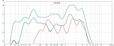
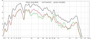
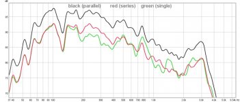
so I did a test 0.6 volt output at speaker terminals it stayed the same over 4 tests spl meter calibrated for graphs 15" dual woofer cabinet
green/black individual drivers measured
blue.........parallel
red...........series
View attachment 656066
Interesting, but...
"dual woofer cabinet" as in ported, sealed, separate enclosures for the woofers in one cabinet or something different?
In Parallel each speaker gets half the power in the sense that if 2 amps are drawn from the AMP, then 1 amp goes to each speaker. But if we consider just the speakers, they both get the same power ... 1 amp each.
Also, consider that Power and Voltage are not linear, there is a SQUARE function in their -
P = E^2 / R
If we have two speakers in Series and we apply a 10v signal, then each speaker gets 5 volts.
P1 = 10^2 / 8 = 12.52w
But each speaker gets half the voltage, so that's 5 volts each.
P2 = 5^2 / 8 = 3.125w
Keep in mind that the power went down because the Impedance went up and therefore the Current went down.
Slightly unrealistic but if we feed a single driver 10 AMPS and a pair of Series Drivers 10 AMPS then we have -
P = I^2 x R
P1 = 100 x 8 = 800w
But, in Series both speakers get the same Current, though they only get half the voltage -
P2 = 100 x 8 = 800w
but that is divided between two speakers, so 400w each.
Parallel drivers get the same Voltage but each consumes half the Current drawn from the amp.
In Series, drivers get the same Current, but half the Voltage.
Though Parallel, while the voltage remains the same, the current draw from the amp is double, as a result the impedance goes down.
In Series, while the current remains the same in both speakers, but voltage goes down (half) per speaker, and the overall Impedance goes up (double).
Steve/bluewizard
Slightly unrealistic but if we feed a single driver 10 AMPS and a pair of Series Drivers 10 AMPS then we have -
P = I^2 x R
P1 = 100 x 8 = 800w
But, in Series both speakers get the same Current, though they only get half the voltage -
P2 = 100 x 8 = 800w
but that is divided between two speakers, so 400w each.
I think your reasoning has gone a little haywire here.
If we feed a 8 ohm driver with 10Amps of current the driving voltage is = to 80volts.
If we feed two 8 ohm drivers connected in series with 10 Amps of current the driving voltage is = to 160 volts. Each driver of that series combination has 80 volts across it not half that of the single driver of P1.
P2 would equal 100 x 16 ohms = 1600 watts.
Actually the current flowing through the series combination should only be 5 amps not the 10 amps that was stated, given the driving voltage is the same.
That would mean the total power dissipation of the series combination would be 400 watts and the power dissipation of each driver would only be 200 watts.
C.M
Last edited:
too much speculation
more data less wank
so I did a test 0.6 volt output at speaker terminals it stayed the same over 4 tests spl meter calibrated for graphs 15" dual woofer cabinet
green/black individual drivers measured
blue.........parallel
red...........series
View attachment 656066
So what does this tell you ?
single vs parallel
60hz +5db
100hz +6db
194hz +7.64db
300hz +9.19db
700hz +4.63db
It proves the +6dB overall in theory as a baseline. All other effects causing these deviations are practical factors shaping the imaging of the drivers, incl. environment, interferences, whaatever.. and pretty much everything else. But the good average is around 6 (6.492 in this very specific case which means in theory again, the +6dB version seems to be closer to reality than the +3dB version. The 6dB believers also told to have +3 and then -3 so overall 0dB gain when in series.. seems to be proven as well, at least for me). Anyway, thanks, great experiment.
Last edited:
...
Actually the current flowing through the series combination should only be 5 amps not the 10 amps that was stated, given the driving voltage is the same.
...C.M
Right I should have done the calculation for both using a fixed voltage. Or I should have derived the Current from a fixed common Voltage.
But the point is the same even if my calculations are off.
In a Parallel circuits with TWO 8 ohms speakers, the total impedance seen by the amp is half that of one driver, or 4 ohms.
In Parallel, but drivers get the same Voltage, but each gets half of the total Current draw from the Amp.
In Series with TWO 8 ohm drivers, the total impedance seen by the amp is 16 ohms. In this case, both speakers get the same Current, but half the applied Voltage.
P = I^2 x R
P = E^2 / R
P = E x I
Steve/bluewizard
Last edited:
Right I should have done the calculation for both using a fixed voltage. Or I should have derived the Current from a fixed common Voltage.
But the point is the same even if my calculations are off.
In a Parallel circuits with TWO 8 ohms speakers, the total impedance seen by the amp is half that of one driver, or 4 ohms.
In Parallel, but drivers get the same Voltage, but each gets half of the total Current draw from the Amp.
In Series with TWO 8 ohm drivers, the total impedance seen by the amp is 16 ohms. In this case, both speakers get the same Current, but half the applied Voltage.
P = I^2 x R
P = E^2 / R
P = E x I
Steve/bluewizard
It is my understanding impedence is not a given but it is frequency dependent according to external elements ?????
It is my understanding impedence is not a given but it is frequency dependent according to external elements ?????
True the rate Impedance is Nominal, meaning "in name only".
Though this is just a bass driver, look at the impedance on this Dayton 6.5" Classic Woofer -
Dayton Audio DC160-8 6-1/2" Classic Woofer
https://www.parts-express.com/pedocs/specs/295-305-dayton-audio-dc160-8-specifications-46146.pdf
The impedance dips to about 6 ohms at 10hz and at 200hz, it peaks at about 68 ohms at 36hz, and from 200hz upward it gradually rises to 84 ohms.
So, yes impedance is complex.
If you are designing crossovers, you design for the impedance at the crossover frequency rather than the nominal impedance.
To deal with the rising impedance at higher frequencies, typically a Zobel Network is used, which can be seen low down at this link -
Crossover Design Chart and Inductance vs. Frequency Calculator(Low-pass)
At higher frequencies the Capacitor becomes a short leaving the Resistor in parallel with the drivers changing impedance. This helps stabilize the impedance at higher frequencies.
But to the core question, while consistently so, a driver's Impedance is all over the place.
Steve/bluewizard
It will be different either side of this crossover frequency, what can be done about this?If you are designing crossovers, you design for the impedance at the crossover frequency rather than the nominal impedance.
It will be different either side of this crossover frequency, what can be done about this?
If you look at these basic crossover design, you input the impedance for each driver. So if one driver is 6.8 ohms and the other driver is 8.2 ohms, enter the numbers and the calculations come out right.
Crossover Design Chart and Inductance vs. Frequency Calculator(Low-pass)
However, if you are referring to a single driver, yes, from the graphs I posted, the frequency is different on each side of the selected crossover frequency, but not by much.
https://www.parts-express.com/pedocs/specs/295-305-dayton-audio-dc160-8-specifications-46146.pdf
But there is a limit to what can be done with passive crossover, but despite that limit, MANY very good sounding speaker are made with passive crossovers.
And, you can use a Zobel Network to, within reason, stablize the impedance.
Steve/bluewizard
What are these limits?But there is a limit to what can be done with passive crossover
- Home
- Loudspeakers
- Multi-Way
- wiring parallel or series sensitivity rules?


