AMV8 said:To all doubters
After trying various combinations of resistor and capacitor I had to conclude that kef were correct.
So doubters I suggest you try this.
Don
Hi,
Dumb rules of thumb even when they apparently work prove nothing
except you do not understand what is actually going on. Applying this
rule to say a 3rd order 300Hz highpass for a midrange unit where you
would end up with around 20R in series with the unit is plainly stupid.
Similarly the same rule applied to a bass unit zobel is also plainly wrong.
") /sreten.
/sreten.sreten said:
Hi,
Dumb rules of thumb even when they apparently work prove nothing
except you do not understand what is actually going on. Applying this
rule to say a 3rd order 300Hz highpass for a midrange unit where you
would end up with around 20R in series with the unit is plainly stupid.
Similarly the same rule applied to a bass unit zobel is also plainly wrong.
you are absolutely right about stupid, the series resistance is frequency dependant. Kef used the best quality elcaps available at that time in the reference series (DF around 5%) and measured them into 1% tolerance bands which were then computer matched to each measured and selected drive unit and inductor to compensate for all the tolerances and get the desired design response. At the 2.5 kHz crossover the 3.3 uF caps in the tweeter section would be around 0.9 ohm. At the 400Hz midrange the 100uF would be around 0.2 ohm. At around 40 Hz where the series 360 uF starts to give the design rolloff it would be around 0.5 ohm. According to this ridiculous rule of thumb you would have to put 36 ohms in series with the bass unit LOL.
See what that would do to your damping and low frequency control
Another critical operating parameter of caps not discussed here so far is ESR (equivalent series resistance). NPE caps are made with an electrolytic (i.e. chemical) paste which can degrade over time depending on a number of environmental factors as well as original build quality. In fact, my expereience is that NPE's seem to have a lifetime similar to foam surrounds in the range of 10-20 yrs.
Many times a NPE's ESR will rise with age and begin to act like a resistor as well - attenuating the treble output of the tweeter.
When someone substitutes the NPE with a film cap, the ESR can drop significantly essentially to zero and thus the new cap sounds harsh to the owner. When, in fact, the tweeter's output has been restored. But after 15 yrs or so, that's been forgotten and all the owner knows is the sound is brighter. Some techie types advocate puting a low value resistor in series with a new film cap when substituting for a NPE cap. Something in the range of .3 to .5 ohms - thus mitigating somewhat objectionable highs now heard.
speakerdoctor said:Another critical operating parameter of caps not discussed here so far
that's exactly what the last two posts were discussing!
Similar problem with KEF Reference Four
Hi,
I am experiencing a similar problem with my KEF Reference Four. I would try to be more specific about the symptoms of the problem.
It seems that in the beginning of the music session, everything seems to be OK. But then the tweeter starts to create a "scratchy sound", or if the music level is low enough, nothing will come out of the tweeter. Playing classical piano pieces shows this problem very well, I guess because of the frequency content and the subtle changes in the music level.
Since this effect seems to have something to do with self-heating and is voltage dependent, I think that I am experiencing problem with the capacitors in the loudspeaker divider network.
Questions:
1. Do you share the same opinion about the source of the problem? Is it possible that there is a bad or oxidized soldering which is starting to behave as a diode, thus the voltage dependance (I checked the tweeter and the PCB on the back of the terminal box, looks OK after a bit of rework)?
2. Where is the MF/HF divider network PCB in the KEF Reference Model Four? The PCB on the back of the terminal box is obviously only the LF filter, since the HF signals are just fed through to a second divider network?
3. Anybody having a schematic of the divider network with component values, which can be posted here or sent to email?
4. Can you suggest a good source of the capacitors I am going to need for refurbishing the divider networks here in Europe, or one operating internationally?
Hope you can help with some good advice, since it is really pitty having such a nice loudspeaker at home and not being able to enjoy it 100%.
Regards
bypass the crossover.
Test the tweeter by connecting direct to the tweeter terminals . Use a capacitor in line and feed from a very quiet signal from the power amplifier.
Has the noise/intermittent off gone?
Try not to solder to the tweeter terminals. If the existing cable is push on, great. If not then try tapping into a bare part of the conductor somewhere along the existing crossover to tweeter line.
Has anybody serviced this type of loudspeaker - KEF Reference Model Four?
Do I really need to desolder the UniQunit, as well as the centre midrange unit, to be able to remove them and access the top part of the cabinet, where it seems that the MF/HF divider network is located?
Regards,
P.
Do I really need to desolder the UniQunit, as well as the centre midrange unit, to be able to remove them and access the top part of the cabinet, where it seems that the MF/HF divider network is located?
Regards,
P.
Intresting thread.
I haved the same problems with Clestion SL6: changing the old electrolyt. Elcap with some polypropylene's like Solen or Mundorf, the sound was not so good. ..but with the new electrolyt's Alcap from FalconAcustic LTD the sound is an improvement,become more more natural.The question is WHY? ..it is possible to be the Alcap superior to any polypropylen's in few Celestion or KEF speakers' projects?
I haved the same problems with Clestion SL6: changing the old electrolyt. Elcap with some polypropylene's like Solen or Mundorf, the sound was not so good. ..but with the new electrolyt's Alcap from FalconAcustic LTD the sound is an improvement,become more more natural.The question is WHY? ..it is possible to be the Alcap superior to any polypropylen's in few Celestion or KEF speakers' projects?
Hi,
Non-polar electrolytics come in two grades < 10% loss
and < 5% loss, and this is usually specified at 1KHz.
Changing capacitor types can change the frequency balance
and / or affect the x/o shape by affecting the filters Q,
especially for the higher loss type.
rgds, sreten.
Non-polar electrolytics come in two grades < 10% loss
and < 5% loss, and this is usually specified at 1KHz.
Changing capacitor types can change the frequency balance
and / or affect the x/o shape by affecting the filters Q,
especially for the higher loss type.
rgds, sreten.
The Celestion SL6 is an early metal dome tweeter with some severe high-Q resonance issues around 18kHz which required a low-impedance notch filter, and will therefore be very sensitive to capacitor ESR. The load and Q seen by the amplifier would be affected too. Celestion also often employed a 4th order bass filter that simply didn't work without some resistance in series with the capacitors. Tinker at your peril, it was known as an amp destroyer anyway!
On the subject of replacing Non-Polars with polypropylene in classic KEF and Celestion speakers, advice depends on circumstances. High Q complex filters are going to be dramatically affected, as are notch filters which may go completely haywire. You can only speculate, but I would expect a lossy capacitor to be a more comfortable load for an amp at supersonic frequencies too.
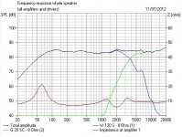
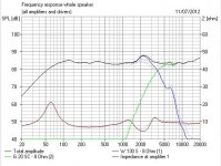
Frequency response changes of 4-6dB and Phase changes of 45 degrees would be expected with critical components like bass shunts and notches. Below is the simulated effect of changing a 15uF (assume 1.5 ohm ESR) non-polar for a polypropylene in a second order bass filter, you must take my word for it that phase alignment (and imaging) gets ruined too. Shocking, isn't it? The exact effect will depend on the filter topology and how load tolerant your amp is, which is probably why no-one will ever agree on this subject.
On the subject of replacing Non-Polars with polypropylene in classic KEF and Celestion speakers, advice depends on circumstances. High Q complex filters are going to be dramatically affected, as are notch filters which may go completely haywire. You can only speculate, but I would expect a lossy capacitor to be a more comfortable load for an amp at supersonic frequencies too.
Frequency response changes of 4-6dB and Phase changes of 45 degrees would be expected with critical components like bass shunts and notches. Below is the simulated effect of changing a 15uF (assume 1.5 ohm ESR) non-polar for a polypropylene in a second order bass filter, you must take my word for it that phase alignment (and imaging) gets ruined too. Shocking, isn't it? The exact effect will depend on the filter topology and how load tolerant your amp is, which is probably why no-one will ever agree on this subject.
Attachments
- Status
- This old topic is closed. If you want to reopen this topic, contact a moderator using the "Report Post" button.
- Home
- Loudspeakers
- Multi-Way
- Capacitor question for KEF speakers.